Eureka AIR delivers breakthrough ideas for toughest innovation challenges, trusted by R&D personnel around the world.

Related identification method for transient electromagnetic weak polarization response

A transient electromagnetic and correlation identification technology, applied in the field of transient electromagnetic exploration, can solve the problems of fast attenuation of the induction field, susceptibility to interference, slow attenuation, etc., to overcome high time cost, reliable observation data, fast and accurate measurement Effect

Pending Publication Date: 2022-05-06
中国地质科学院地球物理地球化学勘查研究所
View PDF0 Cites 0 Cited by
  • Summary
  • Abstract
  • Description
  • Claims
  • Application Information

AI Technical Summary

Problems solved by technology

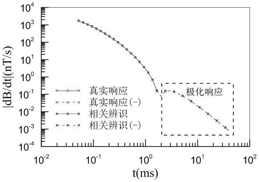
Different from the fast attenuation speed and large initial amplitude of the induction field, the polarization field generally has a small amplitude and slow attenuation speed, so the polarization response shown on the transient electromagnetic curve is generally weaker and more susceptible to interference, and Appeared later
In order to collect more accurate and complete transient electromagnetic weak polarization responses, it is necessary to carry out multiple long-period repeated observations, which requires high time costs and is not economical and practical.
On the other hand, due to the limitation of the repeated observation method, the level of interference suppression depends on the number of observations n, only n -1 / 2 The speed decreases, and it is difficult to obtain good measurement results even if a large amount of observation time is spent when the interference is strong

Method used


Image

  • Related identification method for transient electromagnetic weak polarization response
  • Related identification method for transient electromagnetic weak polarization response
  • Related identification method for transient electromagnetic weak polarization response

Examples


Embodiment Construction

[0024] The following will clearly and completely describe the technical solutions in the embodiments of the present invention with reference to the accompanying drawings in the embodiments of the present invention. Obviously, the described embodiments are only some, not all, embodiments of the present invention. Based on the embodiments of the present invention, all other embodiments obtained by persons of ordinary skill in the art without making creative efforts belong to the protection scope of the present invention.

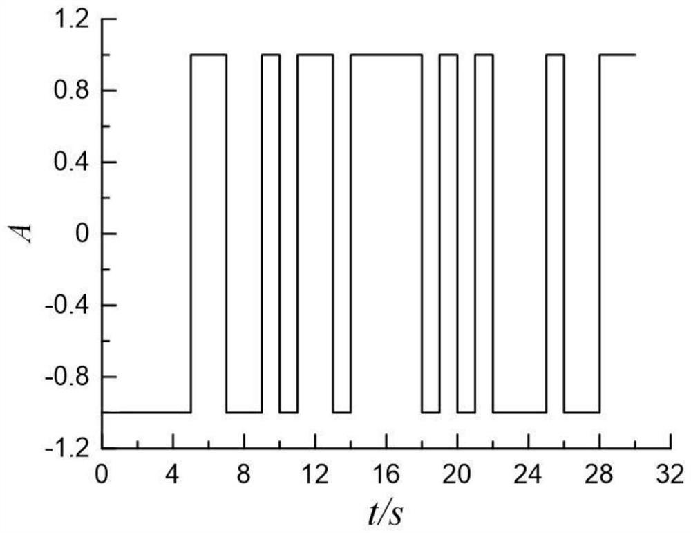
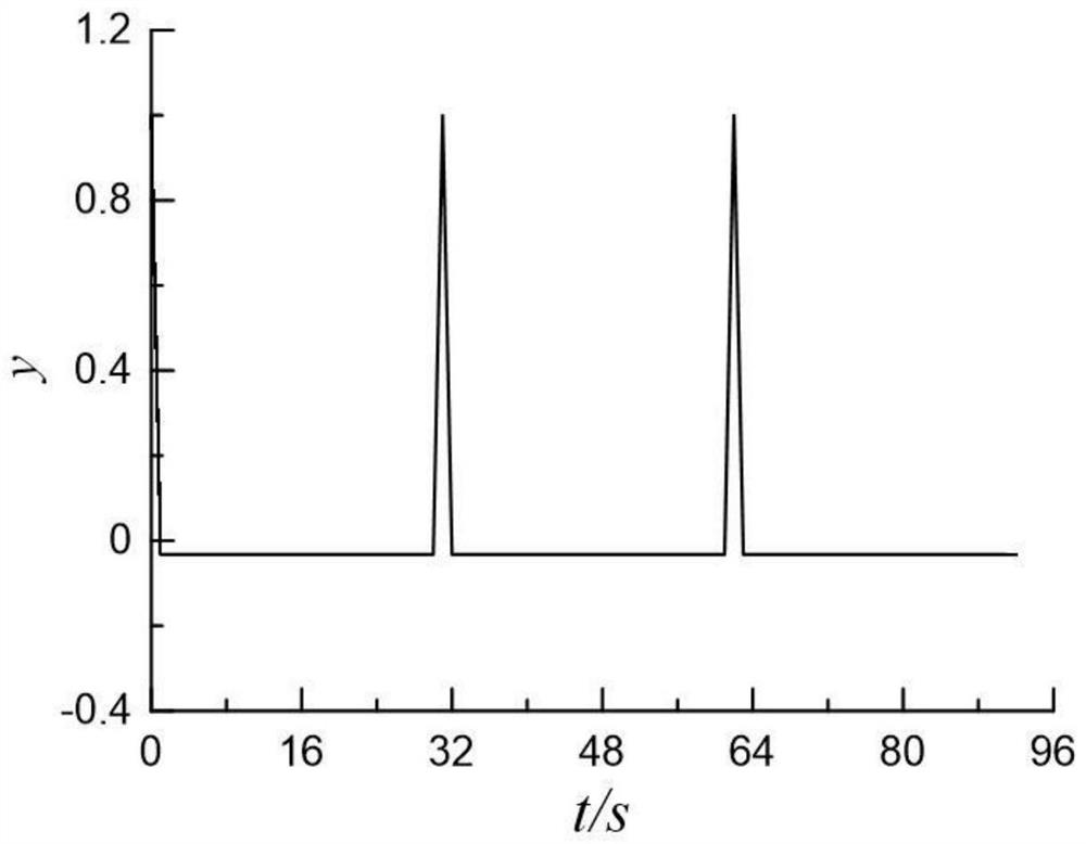
[0025] A correlation identification method for transient electromagnetic weak polarization response, comprising the following steps:

[0026] S1. Set the sampling rate according to the work requirements, select the appropriate transmission waveform according to the autocorrelation function, and determine the transmission parameters such as current size, sequence length, and repeated observation times;

[0027] S2. Start the launch work according to the work de...


PUM


Abstract

The invention belongs to the technical field of transient electromagnetic exploration, and particularly relates to a transient electromagnetic weak polarization response correlation identification method, which comprises the following steps of S1, setting a sampling rate according to a working requirement, selecting a transmitted waveform according to an autocorrelation function, and determining a transmitting parameter; s2, starting transmitting work, and transmitting for one pseudo-random sequence period to serve as a pre-disturbance signal; s3, continuing to transmit the pseudo-random sequence of the next period, and performing full-time sampling on the transmitted waveform and the ground response; s4, stopping transmitting and sampling, and superposing the transmitted waveform and the earth response to obtain a mean value to form transmitted waveform data and earth response data with a periodic pseudo-random sequence length; and S5, respectively calculating a cross-correlation function of the transmitted waveform and the earth response data, carrying out correlation identification calculation, and solving a transient electromagnetic weak polarization response of a periodic pseudo-random sequence length. The transient electromagnetic weak polarization response observation method is used for improving transient electromagnetic weak polarization response observation accuracy and providing reliable observation data for subsequent interpretation work.

Description

technical field [0001] The invention belongs to the technical field of transient electromagnetic exploration, and in particular relates to a correlation identification method of transient electromagnetic weak polarization response. Background technique [0002] Transient electromagnetic method (TEM) is a time-domain electromagnetic prospecting method. The basic principle is to use a grounded or ungrounded emission source to establish a steady magnetic field in the detection area, and then turn off the field source instantaneously. According to Faraday's law of electromagnetic induction, in the underground medium A secondary field that changes with time will be induced, and the induced transient electromagnetic response will be observed and recorded, and the electrical distribution of the underground medium can be inferred through theoretical and numerical simulation analysis. [0003] Due to the induced polarization characteristics of the earth, under the action of ground em...

Claims


Application Information

Patent Timeline
Patent Type & Authority Applications(China)
IPC IPC(8): G01V3/08G01V3/38
CPCG01V3/081G01V3/38
Inventor 智庆全王兴春武军杰邓晓红杨毅张杰
Owner 中国地质科学院地球物理地球化学勘查研究所
Why Eureka
Eureka Blog
Learn More