Waste mask storage device for surgical department
A storage device and department technology, which is applied in the field of waste mask storage device for surgical departments, can solve the problems of cumbersome operation, time-consuming and labor-intensive, low safety, etc., and achieve the effects of high safety, avoiding clumps and knots, and convenient retrieving
- Summary
- Abstract
- Description
- Claims
- Application Information
AI Technical Summary
Problems solved by technology
Method used
Image
Examples
Embodiment 1
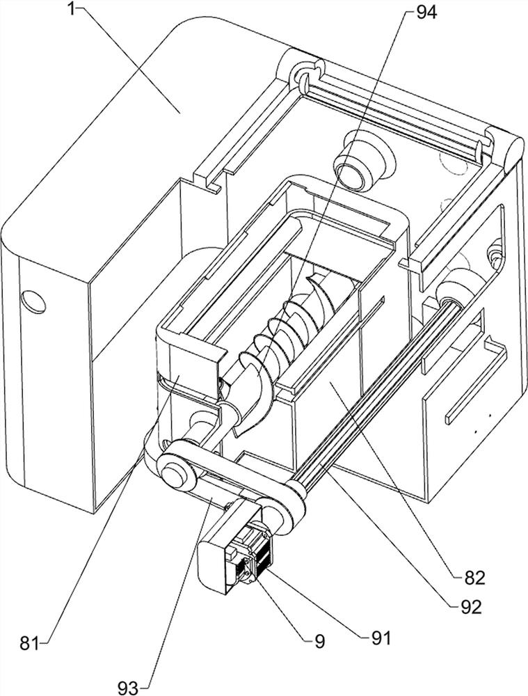
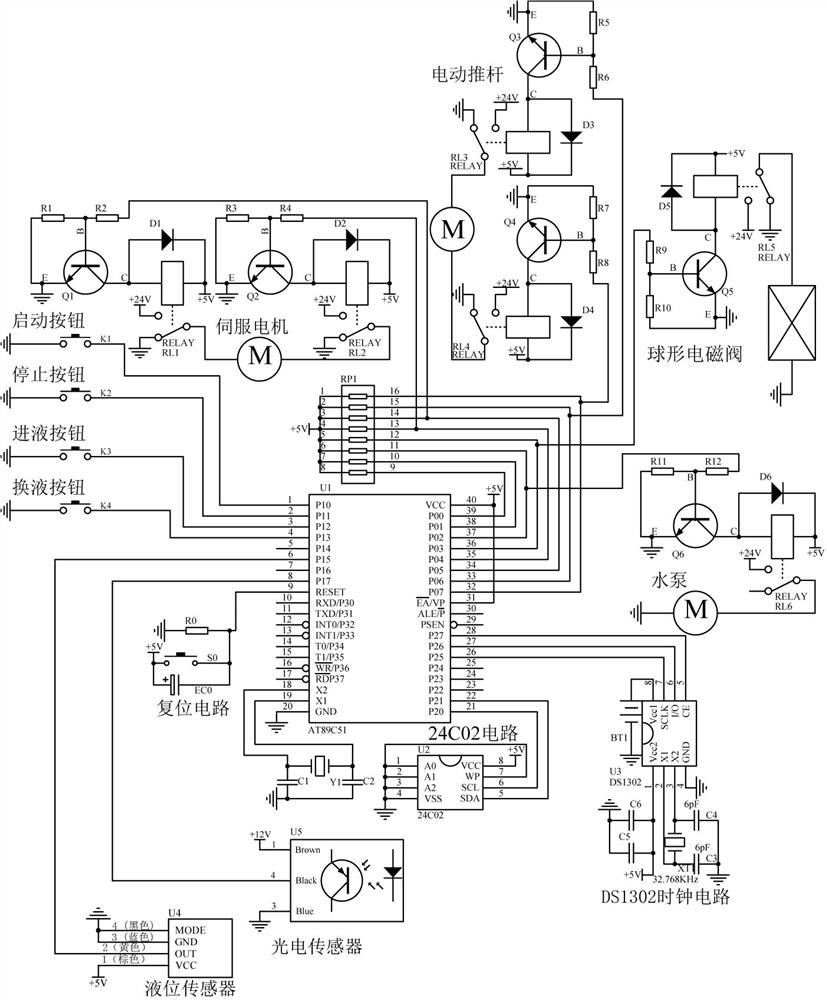
[0084] The utility model relates to a waste mask storage device for surgical departments, such as Figure 1 - Figure 5 As shown in the figure, it includes a box 1, a base 2, an opening and closing top plate 3, a support platform 4, an auxiliary roller 5, an observation window 6, a start button 71, a stop button 72, a storage mechanism 8 and a stirring mechanism 9. The top of the base 2 is provided with a box 1, the top of the box 1 is provided with an opening and closing top plate 3 symmetrically rotating forward and backward, the middle of the right side of the box 1 is provided with a support platform 4, the top of the support platform 4 is provided with a plurality of auxiliary rollers 5 rotating evenly, and the upper left side of the box 1 is provided with an observation window 6, A start button 71 is arranged on the front left side of the upper part of the box 1, a stop button 72 is arranged on the front left side of the upper part of the box 1, the stop button 72 is located o...
Embodiment 2
[0089] On the basis of embodiment 1, such as Figure 6 and Figure 7 As shown, the feeding mechanism 10 also includes a fixed connecting block 101, a sliding gear assembly 102, a first reversing gear assembly 103, a positioning transverse shaft 104, a second transmission assembly 105, a reversing stub shaft 106, a third transmission assembly 107, a feeding rubber wheel 108 and a first rotating shaft 109. A fixed connecting block 101 is arranged on the left front side of the sealing top plate 85, and the fixed connecting block 101 is slidably connected with the positioning bottom frame 81, The lower part of the fixed connecting block 101 is slidably and rotationally connected with the slotted drive shaft 92, the lower part of the fixed connecting block 101 is rotationally provided with a sliding gear assembly 102, the sliding gear assembly 102 is slidably connected with the slotted drive shaft 92, the lower part of the front left side of the inner wall of the box 1 is rotationally pr...
Embodiment 3
[0092] On the basis of embodiment 2, such as Figure 1 、 Figure 8 、 Figure 9 、 Figure 10 、 Figure 11 、 Figure 12 、 Figure 13 and Figure 14 As shown in the figure, it also includes a material distribution mechanism 11. The material distribution mechanism 11 includes a second reversing gear assembly 111, a fourth transmission assembly 112, a positioning cross bar 113, a hollow rotating drum 114, a positioning straight bar 115, a material distribution claw 116, a positioning arc plate 117, a torsion spring 118 and a second rotating shaft 119. A second rotating shaft 119 is arranged at the lower part of the left side behind the inner wall of the box 1, A second reversing gear assembly 111 is arranged between the front side of the second rotating shaft 119 and the rear side of the first rotating shaft 109, the second reversing gear assembly 111 is matched with the sliding gear assembly 102, a positioning cross bar 113 is arranged in the middle of the inner upper part of the box 1, a hol...
PUM
 Abstract
Description
Claims
Application Information
 - R&D Engineer
- R&D Manager
- IP Professional
- Industry Leading Data Capabilities
- Powerful AI technology
- Patent DNA Extraction
Browse by: Latest US Patents, China's latest patents, Technical Efficacy Thesaurus, Application Domain, Technology Topic, Popular Technical Reports.
© 2024 PatSnap. All rights reserved.Legal|Privacy policy|Modern Slavery Act Transparency Statement|Sitemap|About US| Contact US: help@patsnap.com


