
Vertical pneumatic damping grinding machine

A kind of grinding machine and vertical technology, which is applied in the direction of grinding frame, grinding machine parts, grinding machines, etc., can solve the problems of high labor intensity and serious health hazards of workers, so as to improve the quality and efficiency of grinding and ensure rigidity Effect

Pending Publication Date: 2022-05-06
广东博科数控机械有限公司
View PDF0 Cites 0 Cited by
  • Summary
  • Abstract
  • Description
  • Claims
  • Application Information

AI Technical Summary

Problems solved by technology

[0003] The present invention aims to provide a vertical pneumatic shock-absorbing grinder, which can at least solve the problems of high labor intensity and great harm to workers' health in the existing grinding process

Method used


Image

  • Vertical pneumatic damping grinding machine
  • Vertical pneumatic damping grinding machine
  • Vertical pneumatic damping grinding machine

Examples


Embodiment 1

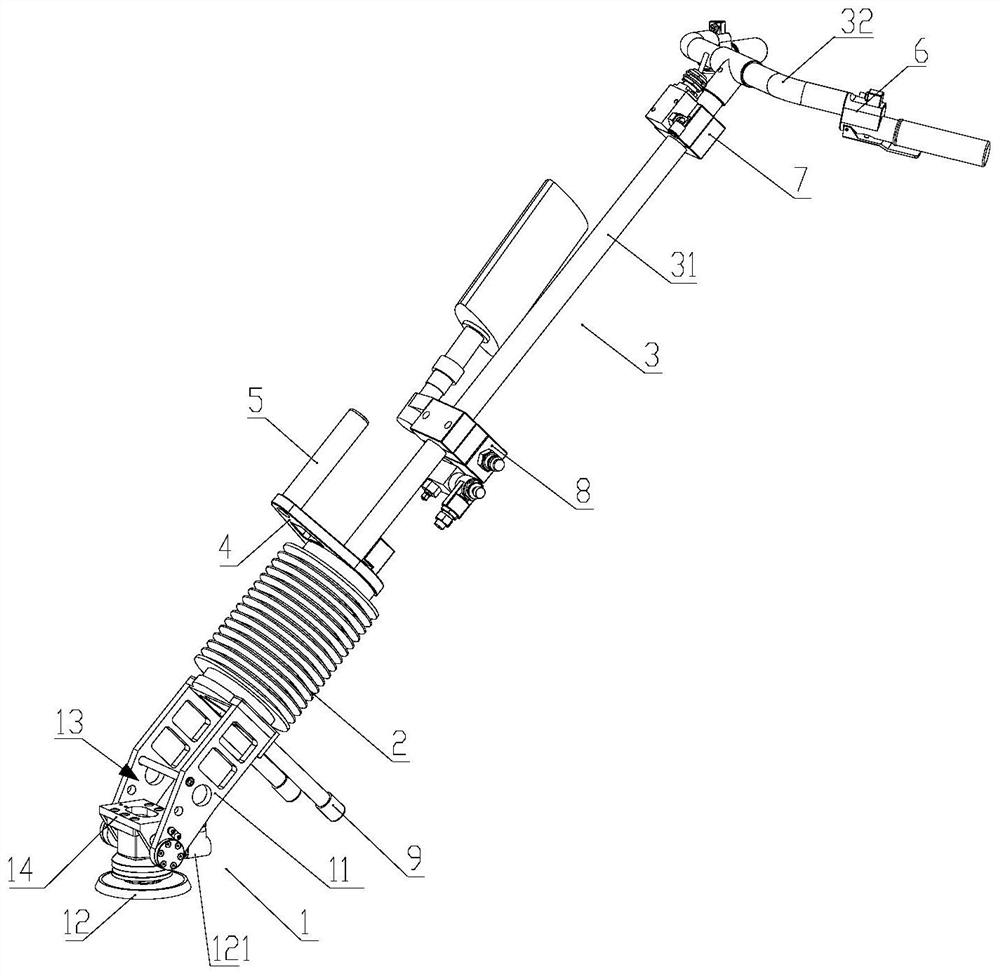
[0058] Such as figure 1 As shown, the vertical pneumatic shock-absorbing grinding machine of this embodiment includes: an end effector 1 , a shock-absorbing device 2 and a control handle 3 .

[0059] Such as figure 1 As shown, the end effector 1 includes at least one grinding bracket 11 and a pneumatic grinding head 12 installed on the grinding bracket 11; in this embodiment, the end effector 1 includes a grinding bracket 11; the pneumatic grinding The head 12 has a pneumatic joint 121 for connecting to an air source, and the air source provides power for the pneumatic grinding head 12 .

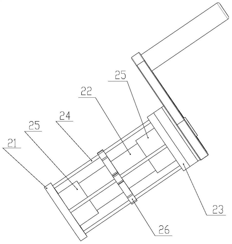
[0060] Such as figure 1 and figure 2 As shown, the shock absorbing device 2 includes a first connecting flange 21, a buffer spring 22, a second connecting flange 23 connected in sequence, and a plurality of pre-tensioned steel wires 24 evenly distributed around the buffer spring 22; wherein the first connection The flange 21 is connected to the grinding bracket 11, and the two ends of e...

Embodiment 2

[0082] The technical scheme of embodiment 2 is basically the same as embodiment 1, and its main difference is: as Figure 6 As shown, the vertical rod 31 forms an obtuse angle with the central axis of the buffer spring 22, and the distance between the horizontal rod 32 and the pneumatic grinding head 12 is the same as the distance between the operator's hand and the desktop when standing. Fitting: the end effector 1 is rotatably connected to the first connecting flange 21 . Specifically, the vertical rod 31 is a short rod, and it forms an obtuse angle with the central axis of the buffer spring 22, so that the operator can directly polish the fixed parts on the desktop or the workbench in a standing posture, which is more ergonomic, and The end effector 1 and the shock absorbing device 2 can rotate relatively, and the end effector 1 can adapt to the deflection angle of the grinding surface during the grinding process.

[0083]In order to facilitate the movement of the vertical...

Embodiment 3

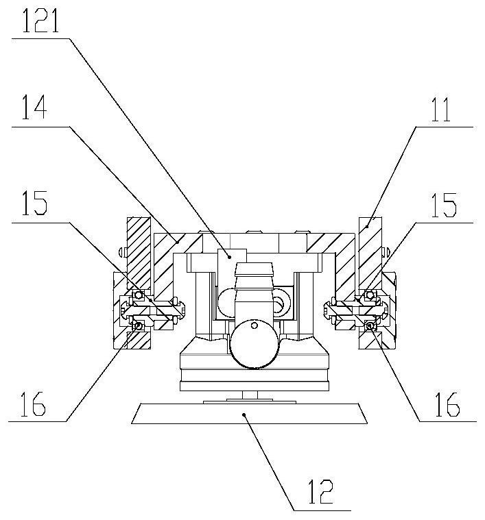
[0085] Such as Figure 8 As shown, the end effector 1 of the vertical pneumatic shock-absorbing grinding machine of this embodiment has two grinding brackets 11, and each grinding bracket 11 is provided with a pneumatic grinding head 12, a grinding fixed plate 14, a rotating shaft 15 and a bearing 16 . The pneumatic grinding head 12 on each grinding support 11 can be rotated independently to adapt to different radians at different positions on the grinding surface.

[0086] It should be noted that Embodiment 3 can be obtained by making improvements on the basis of Embodiment 1 or Embodiment 2. Without affecting understanding, this embodiment only shows a vertical pneumatic shock-absorbing grinder with a long vertical rod .


PUM

PropertyMeasurementUnit
Hardnessaaaaaaaaaa

Abstract

The invention provides a vertical pneumatic damping polisher which comprises an end effector, a pneumatic damping device, a polishing device and a control device. The end effector comprises a polishing support and a pneumatic polishing head. The damping device comprises a first connecting flange, a buffer spring and a second connecting flange which are connected with the polishing bracket, and a plurality of pre-tightening steel wires which are uniformly distributed around the buffer spring; two ends of each pre-tightening steel wire are respectively connected with the first connecting flange and the second connecting flange, so that the buffer spring is in a compressed state; the control handle comprises a vertical rod and a transverse rod, one end of the vertical rod is connected with the second connecting flange, the other end of the vertical rod is connected with the transverse rod, and the transverse rod is used for being held by an operator. According to the grinding machine, by additionally arranging the vertical rod, an operator can conduct grinding in a standing or other comfortable posture, and the grinding machine better conforms to ergonomics and is far away from the grinding face. And the rigidity of the buffer spring is enhanced by adding the pre-tightening steel wire, so that the bending of the damping device caused by the quality of the control handle part and the force applied by an operator is reduced.

Description

technical field [0001] The invention relates to the technical field of grinding equipment, in particular to a vertical pneumatic shock-absorbing grinding machine. Background technique [0002] Aircraft cabins and upper surfaces of wings, ship decks and cabins, auto parts, floors of public transportation equipment, wind turbine blades and other flat or slightly curved planes, rust removal and polishing when new equipment is manufactured or old equipment is repaired. To remove the paint, it is necessary to manually hold the grinder and bend over or half kneel on the workpiece, stretching out the hand and pressing down uncomfortably for grinding. The efficiency is low, and it is easy to suffer from occupational diseases of the wrist; the operator is exposed to the grinding dust at close range, and the working environment is harsh. If he engages in grinding operations for a long time, it will cause irreversible damage to the human body. At the same time, the operator's pressing...

Claims


Application Information

Patent Timeline
IPC IPC(8): B24B27/00B24B41/00B24B41/02B24B47/22
CPCB24B27/0046B24B47/22B24B41/007B24B41/00B24B41/02
Inventor 梁志强董红波赵宏武辛涛李伟龙
Owner 广东博科数控机械有限公司
Learn More