
Laser printing path planning method and laser device

A path planning and laser technology, which is applied in metal processing equipment, welding equipment, manufacturing tools, etc., can solve the problems of long logo printing, affecting laser printing effect, and many filled lines, so as to improve customer satisfaction, Improved laser efficiency and high filling integrity

Pending Publication Date: 2022-05-06
甬矽半导体(宁波)有限公司
View PDF0 Cites 0 Cited by
  • Summary
  • Abstract
  • Description
  • Claims
  • Application Information

AI Technical Summary

Problems solved by technology

[0002] With the rapid development of the semiconductor industry, there is an increasing demand for laser printing in the packaging process, and customers require more and more types and styles of logos to be printed. At this stage, the logo printing method is machine filling. The way of multiple oblique line segments is filled sequentially. This way fills too many lines and too many breakpoints, which leads to a long time and low efficiency of logo printing.
And fill with multiple oblique lines. For logos with a slightly more complex shape, the filling degree is not high, which will affect the laser printing effect and reduce the product yield.

Method used


Image

  • Laser printing path planning method and laser device
  • Laser printing path planning method and laser device
  • Laser printing path planning method and laser device

Examples


Embodiment Construction

[0035] In order to make the purpose, technical solutions and advantages of the embodiments of the present invention clearer, the technical solutions in the embodiments of the present invention will be clearly and completely described below in conjunction with the drawings in the embodiments of the present invention. Obviously, the described embodiments It is a part of embodiments of the present invention, but not all embodiments. The components of the embodiments of the invention generally described and illustrated in the figures herein may be arranged and designed in a variety of different configurations.

[0036] Accordingly, the following detailed description of the embodiments of the invention provided in the accompanying drawings is not intended to limit the scope of the claimed invention, but merely represents selected embodiments of the invention. Based on the embodiments of the present invention, all other embodiments obtained by persons of ordinary skill in the art wi...


PUM


Abstract

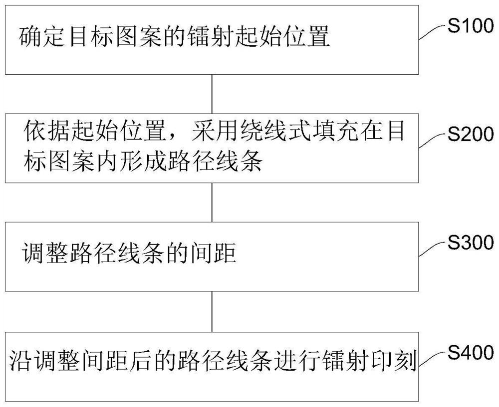
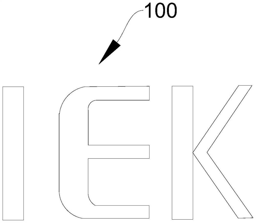
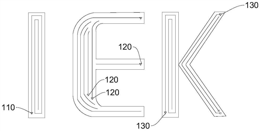
The embodiment of the invention provides a laser lettering path planning method and a laser device, and relates to the technical field of laser imprinting. The laser printing path planning method comprises the following steps: determining a laser starting position of a target pattern; according to the initial position, path lines are formed in the target pattern in a winding type filling mode; adjusting the distance between the path lines; and laser imprinting is carried out along the path lines after the distance is adjusted. Target patterns can be filled more fully in a winding type filling mode, and the laser effect is better; moreover, by adopting a winding type filling path, the idle stroke of machine operation can be greatly reduced, the laser efficiency is higher, and a large amount of time is saved.

Description

technical field [0001] The invention relates to the technical field of laser marking, in particular to a laser printing path planning method and a laser device. Background technique [0002] With the rapid development of the semiconductor industry, there is an increasing demand for laser printing in the packaging process, and customers require more and more types and styles of logos to be printed. At this stage, the logo printing method is machine filling. The method of multiple oblique line segments is filled sequentially. This method fills too many lines and too many breakpoints, which leads to a long time and low efficiency for logo printing. In addition, for a logo with a slightly more complicated shape, the filling degree of multiple oblique lines is not high, which will affect the laser printing effect and reduce the product yield. Contents of the invention [0003] The purpose of the present invention includes, for example, to provide a laser printing path planning...

Claims


Application Information

Patent Timeline
IPC IPC(8): B23K26/362B23K26/70
CPCB23K26/362B23K26/702
Inventor 郑多雄杜如霞李典展李湘渝
Owner 甬矽半导体(宁波)有限公司
Learn More