Device for displaying stress deformation of rigid object
A technology of deforming objects under force, which is applied in the field of devices that display rigid objects deforming under force, and can solve problems such as hard to see, difficult for students to accept the force deformation of rigid objects, etc.
- Summary
- Abstract
- Description
- Claims
- Application Information
AI Technical Summary
Problems solved by technology
Method used
Image
Examples
Embodiment 1
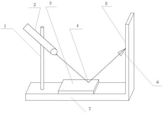
[0009] Put the light source 2 on the light source bracket 1, put the reflective panel 3 on the bottom plate 7, then turn on the light source 2, so that the light of the light source 2 hits the 4 points on the plane of the reflective panel 3 at a certain angle, due to the reflection of the light In principle, the reflected light 6 reflected by the reflective panel 3 hits a point on a surface 5, and then, press the mirror surface with a finger or other things, due to the deformation of the rigid mirror surface, the 4 points on the plane change slightly, but the eyes It is not easy to see, but the position where the reflected light 6 hits a point on a surface 5 is greatly shifted and becomes a point at another position. From the offset angle and the change of the position of the reflection point, it can be seen that the rigid object is deformed by force.
Embodiment 2
[0011] Replace the light source 2 with an ordinary flashlight with good condensing performance, and replace the reflective surface 3 with a reflective mirror, then place the small flashlight on the light source bracket 1, put the reflective panel 3 on the bottom plate 7, and then turn on the light source 2 to make the light source The light of 2 hits the 4 points on the plane of the reflective panel 3 at a certain angle. Due to the principle of light reflection, the reflected light 6 reflected by the reflective panel 3 hits a point on one surface 5, and then, with your finger Or other things press the mirror surface, due to the deformation of the rigid mirror surface, the 4 points on the plane change slightly, but the eyes are not easy to see, but the position of the reflected light 6 to a point on a surface 5 is greatly shifted, becomes a point at another location. From the offset angle and the change of the position of the reflection point, it can be seen that the rigid obje...
Embodiment 3
[0013] Replace the light source 2 with a small laser torch, and replace the glossy surface 3 with a reflective mirror, then place the small laser torch on the light source bracket 1, put the reflective panel 3 on the bottom plate 7, and then turn on the light source 2 to make the small laser torch The light hits 4 points on the plane of the reflective panel 3 at a certain angle. Due to the principle of light reflection, the reflected light 6 reflected by the reflective panel 3 hits a point on a surface 5. Then, use your finger or other When something presses the mirror surface, due to the deformation of the rigid mirror surface, the 4 points on the plane change slightly, but the eyes are not easy to see, but the position of the reflected light 6 to a point on a surface 5 is greatly shifted, becoming point at another location. From the offset angle and the change of the position of the reflection point, it can be seen that the rigid object is deformed by force.
PUM
 Abstract
Description
Claims
Application Information
 - Generate Ideas
- Intellectual Property
- Life Sciences
- Materials
- Tech Scout
- Unparalleled Data Quality
- Higher Quality Content
- 60% Fewer Hallucinations
Browse by: Latest US Patents, China's latest patents, Technical Efficacy Thesaurus, Application Domain, Technology Topic, Popular Technical Reports.
© 2025 PatSnap. All rights reserved.Legal|Privacy policy|Modern Slavery Act Transparency Statement|Sitemap|About US| Contact US: help@patsnap.com

