
High-strength PTFE synchronous belt and preparation method thereof

A technology of PTFE and synchronous belts, which is applied in the direction of belts, transmission belts, mechanical equipment, etc., can solve the problem that PTFE coating is difficult to compound with tooth cloth layer, and achieve the effect of avoiding short board effect and reducing requirements

Pending Publication Date: 2022-05-03
NINGBO FENGMAO FAR EAST RUBBER
View PDF1 Cites 0 Cited by
  • Summary
  • Abstract
  • Description
  • Claims
  • Application Information

AI Technical Summary

Problems solved by technology

[0003] In order to overcome the problem that the PTFE coating is difficult to be combined with the tooth cloth layer, the present invention provides a high-strength PTFE timing belt. The PTFE coating can be combined with the tooth cloth layer through a calender after modification.

Method used


Image

  • High-strength PTFE synchronous belt and preparation method thereof
  • High-strength PTFE synchronous belt and preparation method thereof

Examples


Embodiment 1

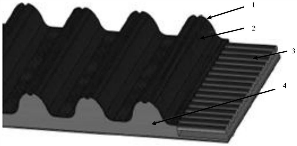
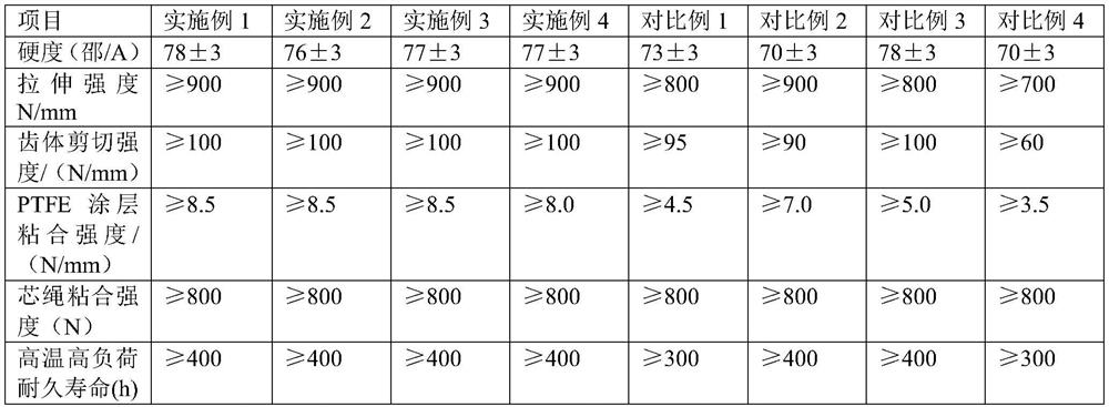
[0021] A high-strength PTFE timing belt, such as figure 1 As shown, it is composed of rubber layer 4, wire rope 3, tooth cloth layer 2 and PTFE coating 4. The material of the rubber layer 4 is HNBR containing aramid staple fibers, and the mass ratio of HNBR and aramid staple fibers is 100:4. The addition of aramid staple fibers can significantly improve the modulus of modulus and modulus of the rubber layer under small strains. . The rubber layer 4 is embedded with several wire ropes 3 arranged in parallel along the length direction. The wire ropes 3 are HNBR glass fiber wire ropes, that is, the surface of the glass fiber is impregnated with HNBR latex to improve the fatigue resistance of the wire ropes. One side surface of the rubber layer 4 is in the shape of a continuous tooth, and the surface is provided with a tooth cloth layer 2, and the tooth layer 2 is made of nylon elastic cloth. The surface of tooth cloth layer 2 is coated with modified PTFE coating 1, and the prep...

Embodiment 2

[0026] The difference with Example 1 is that the mass ratio of HNBR and aramid staple fiber in the rubber layer 4 is 100:1; in the preparation method of modified PTFE coating 1, surface-modified PTFE and ZDMA are by mass ratio 100:5 Mixing, surface-coated PTFE and HNBR are mixed at a mass ratio of 1.6:1.

Embodiment 3

[0028] The difference with Example 1 is that the mass ratio of HNBR and aramid staple fiber in the rubber layer 4 is 100:5; in the preparation method of modified PTFE coating 1, surface-modified PTFE and ZDMA are by mass ratio 100:20 Mixing, surface-coated PTFE and HNBR are mixed at a mass ratio of 2:1.


PUM

PropertyMeasurementUnit
poweraaaaaaaaaa

Abstract

The invention relates to the field of synchronous belts, and provides a high-strength PTFE synchronous belt aiming at the problem that a PTFE coating of the synchronous belt is difficult to be compounded with a tooth cloth layer, the high-strength PTFE synchronous belt comprises a rubber layer, the rubber layer is made of HNBR, a rope is embedded in the rubber layer in the length direction, the surface of one side of the rubber layer is in a continuous wheel tooth shape, the tooth cloth layer and the modified PTFE coating are arranged on the surface, and the tooth cloth layer and the modified PTFE coating are arranged on the rubber layer. And the modified PTFE coating is combined with the tooth cloth layer through a calender. According to the invention, the PTFE coating is modified, so that the PTFE coating can be combined with the tooth cloth layer through the calender. The invention also provides a preparation method of the high-strength PTFE synchronous belt, which comprises the following steps: (1) pretreating the tooth cloth layer by using RFL, pasting the modified PTFE coating on the tooth cloth layer, and compounding through a calender to obtain a composite layer; and (2) combining the composite layer with the rubber layer, and vulcanizing to obtain the synchronous belt.

Description

technical field [0001] The invention relates to the field of synchronous belts, in particular to a high-strength PTFE synchronous belt and a preparation method thereof. Background technique [0002] Synchronous belt is a kind of conveyor belt, which combines the advantages of belt transmission, chain transmission and gear transmission. During transmission, the power is transmitted through the meshing of the teeth of the synchronous belt and the tooth grooves of the synchronous pulley. It does not need lubrication and is non-polluting. It is a relatively Ideal conveyor belts are widely used in industrial manufacturing and transmission in various industries. Synchronous belts will inevitably wear out after a period of use, and how to improve the wear resistance of synchronous belts has also been a subject of research. The patent EP1157813A1 covers the surface of the synchronous belt with a polytetrafluoroethylene wear-resistant layer to prolong the service life of the synchro...

Claims


Application Information

Patent Timeline
Patent Type & Authority Applications(China)
IPC IPC(8): F16G1/28D06N3/04B29D29/08
CPCF16G1/28D06N3/047B29D29/08
Inventor 蒋春雷黄振东董勇修戚好来谢军军
Owner NINGBO FENGMAO FAR EAST RUBBER
Learn More