Display device

Pending Publication Date: 2022-04-29
JAPAN DISPLAY INC
View PDF2 Cites 0 Cited by
  • Summary
  • Abstract
  • Description
  • Claims
  • Application Information

AI Technical Summary

Problems solved by technology

In this case, there is a possibility that the shading of light may be visually recognized as streaked unevenness.

Method used


Image

  • Display device
  • Display device
  • Display device

Examples


Embodiment Construction

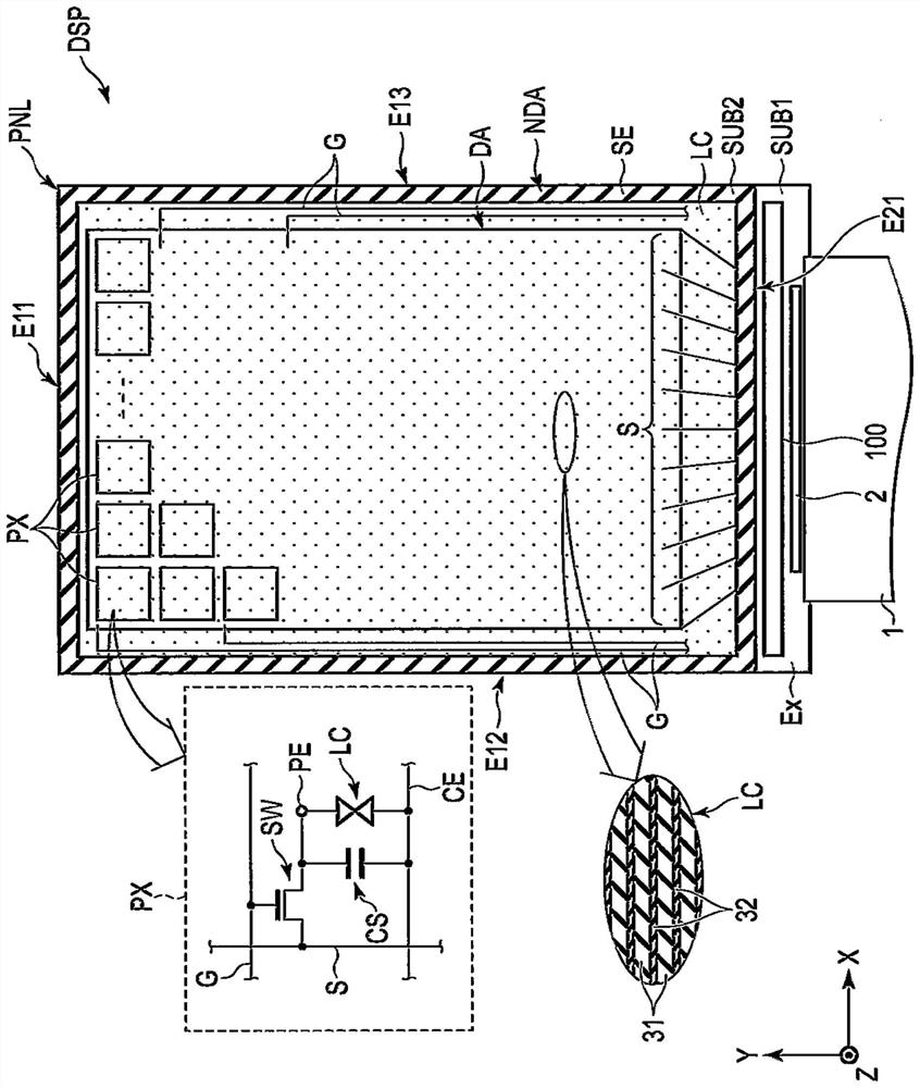
[0035] Below, refer to the attachment Figure IThe present embodiment will be described next. In addition, the disclosure is only an example. For those skilled in the art, appropriate changes that can maintain the gist of the invention and are easy to think of are certainly included in the scope of the invention. In addition, in order to make the description of the drawings more clear, there are cases where the width, thickness, shape, etc. of each part are schematically represented compared with the actual way, but it is only an example and does not limit the interpretation of the invention. In addition, in this specification and the drawings, the constituent elements that play the same or similar functions with respect to the elements described in the existing drawings are marked with the same reference numerals, and sometimes the repeated detailed description is appropriately omitted.

[0036] Figure 1 Is a top view showing a configuration example of the display device DSP of t...


PUM


Abstract

The purpose of the present embodiment is to provide a display device capable of suppressing a reduction in display quality. A display device according to an embodiment includes: a display panel including a polymer dispersed liquid crystal layer; and a light-emitting module provided along a side surface of the display panel, the light-emitting module including: a first light source having a first light-emitting point; a second light source having a second light emitting point having the same color as the first light emitting point; the first light guide body is arranged between the first light source and the side surface; and a second light guide body which forms a contact portion in contact with the first light guide body and is provided between the second light source and the side surface, the first light guide body and the second light guide body being arranged in a first direction, the distance between the contact part and the first light-emitting point along the first direction is equal to the distance between the contact part and the second light-emitting point along the first direction.

Description

technical field [0001] The embodiment of the invention relates to a display device. Background technology [0002] In recent years, various lighting devices with light modulation elements that exhibit scattering or transparency to light have been proposed. In one example, the light modulation element has a polymer dispersed liquid crystal layer as the light modulation layer. The light modulation element is arranged behind the light guide plate to scatter the light incident from the side of the light guide plate. [0003] The light emitted from a plurality of light-emitting elements arranged at intervals diffuses and propagates inside the light guide plate. In the area near the light-emitting element in the light guide plate, there is a case that the light from each light-emitting element is not fully mixed with each other. In this case, there is a hidden danger that the light intensity is visually recognized as stripe unevenness. [0004] Existing technical literature [0005] Pa...

Claims


Application Information

Patent Timeline
IPC IPC(8): G02F1/13357G02F1/1334
CPCF21S2/00G02F1/133615G02B6/0068G02B6/0083G02B6/0086G02B6/0073G02F1/1334
Inventor 苟正祎川上久德
Owner JAPAN DISPLAY INC
Why Eureka
Try Eureka