
Disassembling and assembling tool for rotor of hub motor

A hub motor and rotor technology, applied in the direction of electromechanical devices, manufacturing tools, manufacturing motor generators, etc., can solve the problems of low disassembly and assembly efficiency, collision between rotor and stator, large footprint of horizontal structure, etc., to achieve the disassembly process Stable and safe, improve the efficiency of disassembly and assembly, and move smoothly

Inactive Publication Date: 2022-04-29
河北瑞兆激光再制造技术股份有限公司
View PDF3 Cites 0 Cited by
  • Summary
  • Abstract
  • Description
  • Claims
  • Application Information

AI Technical Summary

Problems solved by technology

Due to the special structure of this kind of permanent magnet hub motor with outer rotor, the assembly gap between the rotor and the stator is very small, and because of the magnetism, if there is no external force guidance during assembly, it is easy to cause the rotor and stator to collide. The hub motor is usually large. Mass production, so a dedicated tool is required to ensure efficient and smooth process of removing and assembling the rotor
[0003] Many existing rotor disassembly tools for permanent magnet hub motors have a horizontal structure, and the installation of the rotor and stator is realized by applying force in the horizontal direction. However, in actual use, the installation effect is not as good as expected, and the horizontal structure occupies an area of The area is large, external force control is required at each stage of assembly and disassembly, and the stability is poor. When the attractive and repulsive forces act, the position of the rotor is prone to shift, and the disassembly efficiency is low.

Method used


Image

  • Disassembling and assembling tool for rotor of hub motor
  • Disassembling and assembling tool for rotor of hub motor
  • Disassembling and assembling tool for rotor of hub motor

Examples


Embodiment Construction

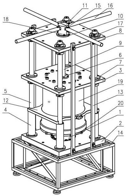
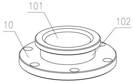
[0023] Such as Figure 1-5 As shown, the in-wheel motor rotor dismounting tool includes a base 14 on which a bottom plate 2 is mounted, and a sliding guide mechanism and a rotating mechanism are mounted on the bottom plate 2 .

[0024] A base 1 is arranged in the center of the bottom plate 2, and the stator 20 is fixedly installed on the base 1 through connecting pieces such as bolts.

[0025] The sliding guide mechanism includes a slide plate 3, a top plate 8, a guide rail 5 and a guide sleeve 4; the rotor 19 is placed on the stator 20, and the slide plate 3 is installed on the top of the rotor 19. The bottom plate 2 is provided with a guide sleeve 4, and the lower part of the guide rail 5 is placed in the guide sleeve 4; the upper part of the guide rail 5 passes through the slide plate 3 and is connected with the top plate 8. The rotating mechanism includes a lead screw 9, a top cover 11 and a lead screw seat 6; the lead screw seat 6 is arranged at the central position of t...


PUM


Abstract

A hub motor rotor dismounting tool is characterized in that a base plate is mounted on a base, and a sliding guide mechanism and a rotating mechanism are mounted on the base plate; a base is arranged in the center of the bottom plate; a sliding plate is mounted at the top of the rotor; a guide sleeve is arranged on the bottom plate; the lower part of the guide rail is arranged in the guide sleeve; the upper part of the guide rail penetrates through the sliding plate; the lead screw seat is arranged in the center of the sliding plate; the lower part of the lead screw is movably connected with the lead screw seat; the upper part of the screw penetrates through the center of the top plate; the top cover is arranged at the upper end of the lead screw; a connecting plate is arranged in the top cover, and the free end of the connecting plate is sleeved with a sleeve. The device is high in self-locking performance, the disassembly and assembly efficiency is improved, the guide rail and the lead screw are positioned in a high-precision mode, and the disassembly and assembly process is stable and safe.

Description

technical field [0001] The invention relates to a disassembly and assembly tool, in particular to a disassembly and assembly tool suitable for hub motor rotors. Background technique [0002] The hub motor is a motor form commonly used in automobile tires. The hub motor has a unique outer rotor structure, that is, the stator is fixed on the inside, and the rotor rotates around the stator on the outside. Such an outer rotor hub motor is usually a permanent magnet motor with magnetically conductive material on the inner wall of the rotor. When the rotor is installed on the stator, after the rotor enters the first half of the stator, their magnetism repels each other, and an external force is required to keep the rotor installed, and when they enter the second half, their magnetism attracts each other, and the rotor and stator can be automatically adsorbed together. Due to the special structure of this kind of permanent magnet hub motor with outer rotor, the assembly gap betwee...

Claims


Application Information

Patent Timeline
Patent Type & Authority Applications(China)
IPC IPC(8): H02K15/00B25B27/14
CPCH02K15/0006B25B27/14
Inventor 韩宏升刘立歧苏艳丽蔡之城赵鸣鸣王健赵稳政雷剑波董世运韩金虎王东旭赵静超
Owner 河北瑞兆激光再制造技术股份有限公司
Learn More