Electrical power distribution cabinet for photovoltaic power station

A photovoltaic power station, electric power technology, applied in the field of power distribution cabinets, can solve problems such as humidity, poor heat dissipation, and instrument damage, and achieve high efficiency

Pending Publication Date: 2022-04-29
华能青海发电有限公司
View PDF1 Cites 1 Cited by
  • Summary
  • Abstract
  • Description
  • Claims
  • Application Information

AI Technical Summary

Problems solved by technology

[0003] At present, the existing power distribution cabinet lacks a dehumidification mechanism, which cannot remove moisture in time, and it is difficult to ensure that the circuit will not fail due to moisture, and the heat dissipation efficiency is not high. According to the patent No. CN 106953258 A published by China Patent Network A power distribution cabinet body with heat dissipation function, the patent discloses a power distribution cabinet body with heat dissipation function, including the power distribution cabinet body, the interior of the power distribution cabinet body is equipped with The inner shell, the bottom of the electric power distribution cabinet body is provided with a mounting base plate, and both ends of the mounting base plate are fixedly connected with the inner surface of the inner shell
Through the operation of the heat dissipation fan, cold air is generated, and through the connection of the air pipe, the cold air enters the interior of the power distribution room to dissipate heat from the equipment in the power distribution room, and the cooling water takes away the power distribution in the flow of cooling and heat dissipation The heat in the room realizes the heat dissipation treatment of the power distribution room, which is convenient for the heat dissipation fan to discharge the internal heat to the main body of the power distribution cabinet through the function of the heat dissipation port, achieving the advantage of having the heat dissipation function, thereby effectively dissolving the center It solves the problem that the poor heat dissipation effect of the existing electric power distribution cabinet is likely to cause damage to the internal equipment of the electric power distribution cabinet; however, there are still problems in this patent. Dust, and it is easy to bring moist gas, which will affect the internal electrical equipment and cause circuit failure

Method used


Image

  • Electrical power distribution cabinet for photovoltaic power station
  • Electrical power distribution cabinet for photovoltaic power station
  • Electrical power distribution cabinet for photovoltaic power station

Examples


Embodiment 1

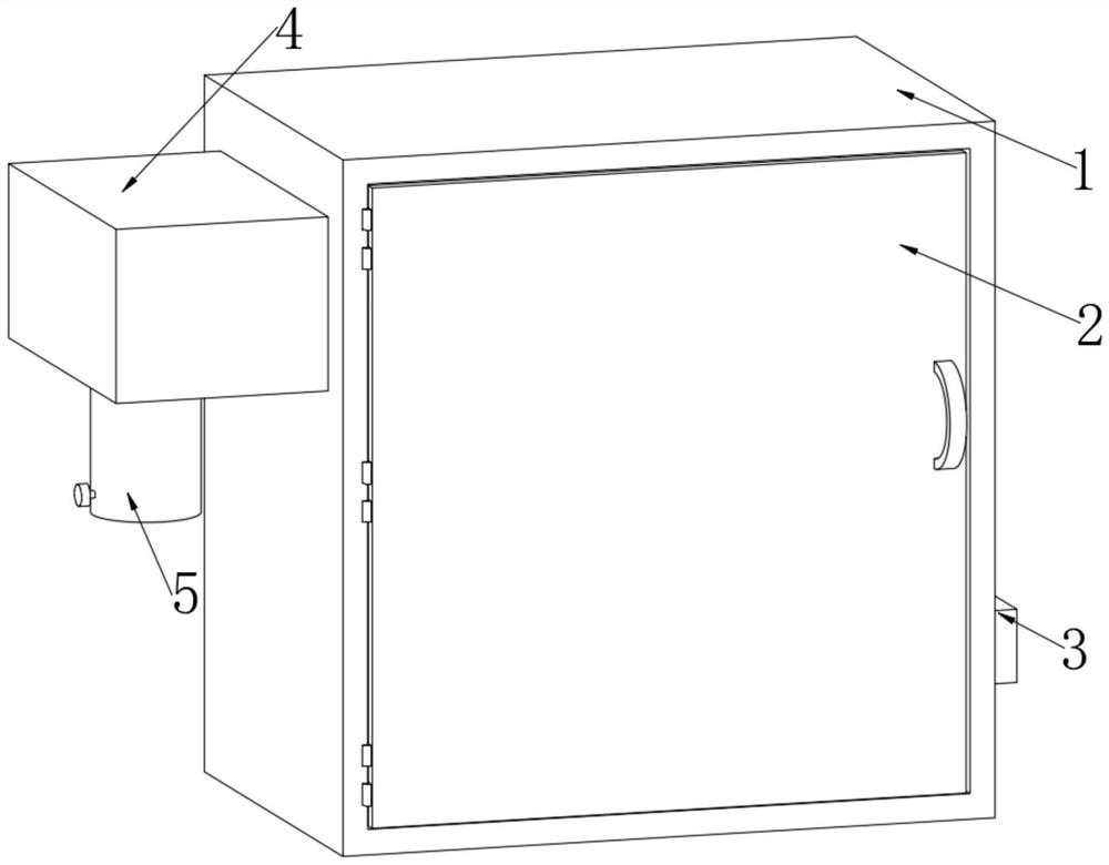
[0031] like Figure 1-Figure 4 , Figure 8 As shown, the embodiment of the present invention provides a power distribution cabinet for a photovoltaic power station, including a power distribution cabinet body 1, a control circuit board is arranged inside the power distribution cabinet body 1, and the inner wall of the power distribution cabinet body 1 is rotatably installed There is a cabinet door 2, an air pump 3 is fixedly installed on one side of the power distribution cabinet body 1, and an air outlet pipe 7 is fixedly sleeved on one side of the air suction pump 3, and one end of the air outlet pipe 7 runs through the power distribution cabinet body 1, and the power distribution cabinet One side of the body 1 is provided with a dehumidification mechanism 4;

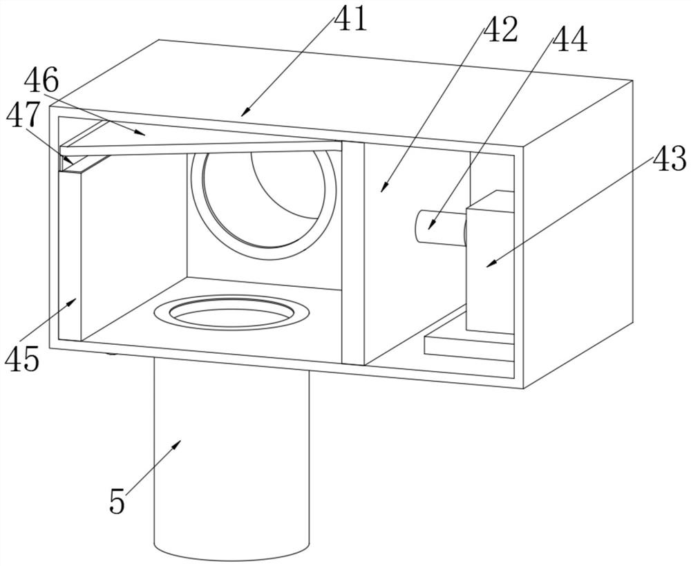
[0032] The dehumidification mechanism 4 includes a dehumidification box 41, the inner wall of the dehumidification box 41 is fixedly equipped with a partition 42, the inside of the dehumidification box 41 is located ...

Embodiment 2

[0042] like Figure 1-Figure 8 As shown, the difference between Embodiment 2 and Embodiment 1 is that it is added: a liquid storage tank 8 is provided on the outside of the power distribution cabinet body 1, a liquid replenishment pipe is provided on the top of the liquid storage tank 8, and the outside of the power distribution cabinet body 1 is fixed. A support plate is installed, and a cooling water pump 9 is detachably installed on the top surface of the support plate. One end of the cooling water pump 9 is fixedly sleeved with a first water pipe 10, and the other end of the cooling water pump 9 is fixedly sleeved with a second water pipe 11. The second water pipe One end of 11 is connected to a vertical pipe 12, and one side of the vertical pipe 12 is connected to a cooling water pipe 16, and one end of the cooling water pipe 16 is detachably installed with an atomizing spray cover 17, and the inner wall of the power distribution cabinet body 1 is fixedly installed with co...


PUM


Abstract

The invention discloses an electrical power distribution cabinet for a photovoltaic power station, and particularly relates to the technical field of power distribution cabinets, the electrical power distribution cabinet comprises a power distribution cabinet body, a control circuit board is arranged in the power distribution cabinet body, a cabinet door is rotatably mounted on the inner wall of the power distribution cabinet body, and an air pump is fixedly mounted on one side of the power distribution cabinet body; and one side of the air extracting pump is fixedly sleeved with an air outlet pipe. The device effectively solves the problem that a dehumidification mechanism is lacked in a current power distribution cabinet, achieves the purpose of dehumidifying the interior of the power distribution cabinet through air exchange and dehumidification of entering gas, is higher in safety compared with a mode of directly inputting high-temperature gas into the power distribution cabinet, possibly causes internal electrical equipment to be scrapped due to high temperature, and reduces the production cost. The workload of the heat dissipation mechanism is also increased; in addition, the heat dissipation mechanism starts from the inner part and the outer part, heat dissipation is carried out on the control circuit board through a condensation pipe and heat dissipation fins, dust or moisture cannot enter the interior of the power distribution cabinet body while heat dissipation is carried out, and therefore normal use of the power distribution cabinet is not affected.

Description

technical field [0001] The invention relates to the technical field of power distribution cabinets, and more specifically, the invention relates to a power distribution cabinet for photovoltaic power stations. Background technique [0002] The power distribution cabinet (box) is divided into power distribution cabinet (box), lighting distribution cabinet (box), metering cabinet (box), and is the final equipment of the power distribution system. The power distribution cabinet is a general term for the motor control center. The power distribution cabinet is used in the occasions where the load is relatively scattered and there are few circuits; the motor control center is used in the occasions where the load is concentrated and there are many circuits. They distribute the electric energy of a certain circuit of the upper-level power distribution equipment to the nearest load. This level of equipment shall provide protection, monitoring and control of the load. [0003] At p...

Claims


Application Information

Patent Timeline
Patent Type & Authority Applications(China)
IPC IPC(8): H02B1/28H02B1/30H02B1/56H02B1/24H02S40/30
CPCH02B1/30H02B1/306H02B1/565H02B1/28H02B1/24H02S40/30Y02E10/50
Inventor 史国全王金鑫朱耿峰张佳李海建杨雪峰孙超伏林李肖肖孙浩
Owner 华能青海发电有限公司
Why Eureka
Try Eureka