Polarization measurement method and system for improving array direction finding precision, and storage medium
A measurement method and direction finding technology, applied in radio wave measurement systems, direction finders for direction determination, direction finders using radio waves, etc. Problems such as the influence of electromagnetic reflection on the surrounding installation platform environment, etc., to achieve the effects of insensitive polarization purity, good real-time performance, and easy implementation
- Summary
- Abstract
- Description
- Claims
- Application Information
AI Technical Summary
Problems solved by technology
Method used
Image
Examples
Embodiment 1
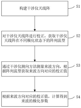
[0040] see figure 1 , the present invention provides an embodiment of a polarization measurement method for improving the accuracy of array direction finding, the method comprising the following steps:
[0041] S1, building an interferometer antenna array;
[0042] S2. Calibrate the interferometer antenna array to obtain array flow patterns of the interferometer antenna array in different polarization states;
[0043] Specifically, performing calibration on the interferometer antenna array includes performing horizontal and vertical polarization calibration or other orthogonal polarization calibration on the interferometer antenna array. Wherein, other orthogonal polarizations may be right-handed circular polarizations or ±45-degree oblique polarizations.
[0044] Specifically, the array flow pattern is a horizontally polarized wave and a vertically polarized wave or other orthogonally polarized waves respectively received by each element unit in the interferometer antenna a...
Embodiment 2
[0085] The following describes an implementation example of a 4-element antenna array.
[0086] see figure 2 , the antenna array includes 3 left-handed circularly polarized helical antennas and 1 right-handed circularly polarized helical antenna, and the 3 left-handed circularly polarized helical antennas constitute a traditional 3-unit single-polarization interferometer antenna array. On the basis of the 3-unit single-polarization interferometer antenna array, a right-handed circularly polarized helical antenna is added.
[0087] Correct the horizontal and vertical polarization of the interferometer antenna array in the microwave anechoic chamber, and obtain the array flow patterns of the array in the horizontal and vertical polarization states and . The corrected angle range is consistent with the range of the direction-finding field of view, the corrected frequency band is consistent with the required measurement frequency band, and the array flow pattern is processed...
Embodiment 3
[0093] see Figure 4 , the present invention also provides an embodiment of a polarization measurement system for improving the accuracy of array direction finding, including:
[0094] Construction module 101, for constructing interferometer antenna array;
[0095] An acquisition module 102, configured to calibrate the interferometer antenna array, and acquire array flow patterns of the interferometer antenna array in different polarization states;
[0096] The correction module 103 is used to measure the incoming wave direction by the interferometer direction finding method, and obtain the correction value corresponding to the incoming wave direction according to the array flow pattern;
[0097] The calculation module 104 is configured to calculate the horizontal polarization component and the vertical polarization component through polarization decomposition according to the correction value corresponding to the incoming wave direction, so as to obtain the polarization para...
PUM
 Abstract
Description
Claims
Application Information
 - Generate Ideas
- Intellectual Property
- Life Sciences
- Materials
- Tech Scout
- Unparalleled Data Quality
- Higher Quality Content
- 60% Fewer Hallucinations
Browse by: Latest US Patents, China's latest patents, Technical Efficacy Thesaurus, Application Domain, Technology Topic, Popular Technical Reports.
© 2025 PatSnap. All rights reserved.Legal|Privacy policy|Modern Slavery Act Transparency Statement|Sitemap|About US| Contact US: help@patsnap.com


