Protective cover structure for machining equipment

A technology of mechanical processing and protective cover, which is applied in the field of protective cover, can solve the problems of gaps in the closure, occupying space, and ineffective closing between sliding doors, etc., so as to increase airtightness, increase airtightness and durability Effect

Inactive Publication Date: 2022-04-29
湖州天祺自动化科技有限公司
View PDF0 Cites 0 Cited by
  • Summary
  • Abstract
  • Description
  • Claims
  • Application Information

AI Technical Summary

Problems solved by technology

[0005] The present invention provides a protective cover structure for mechanical processing equipment, one purpose of which is to have the characteristics of sealing between sliding doors to increase airtightness and durability, and to solve the problem of leaving gaps in the closing parts caused by long-term use , leading to the inability to effectively close the sliding doors, and the debris and harmful gases generated during internal processing will float out; another purpose is to solve the problem that the volume of debris is relatively large and the interior is hollow. With the accumulation of debris, it will take up a lot of space inside, and it needs to be cleaned many times, which is a troublesome problem, so as to achieve the effect of compressing the cleaned debris and increasing the internal collection space

Method used


Image

  • Protective cover structure for machining equipment
  • Protective cover structure for machining equipment
  • Protective cover structure for machining equipment

Examples


Embodiment 1

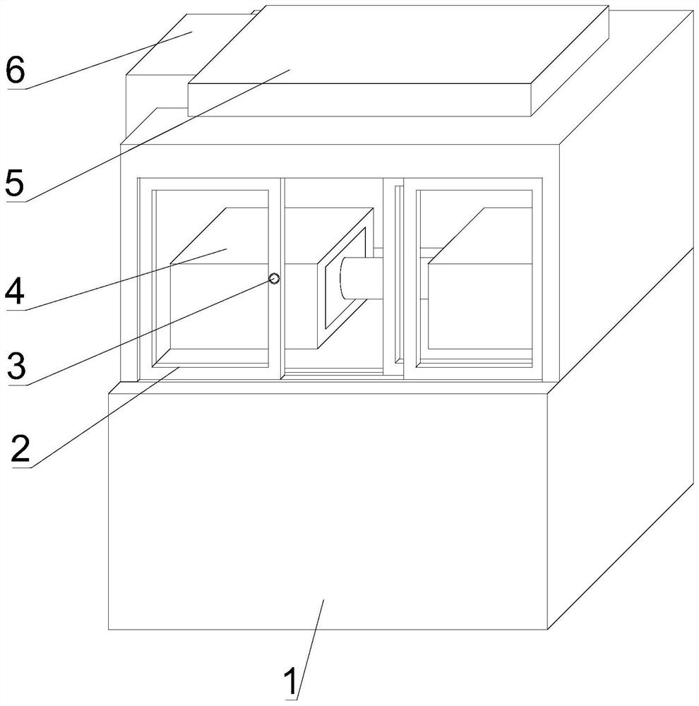
[0039] Such as Figure 1-7As shown, the present invention provides a protective cover structure for mechanical processing equipment, including a waste cooling device 1, a movable and closed protective glass door 2, a locking button 3, a material processor 4, a suction plate 5, and a purification air duct 6 and a workbench, a workbench is arranged on the top outer surface of the waste cooling device 1, a movable and closed protective glass door 2 is arranged on the outer surface of the workbench, and a locking button 3 is arranged on the outer surface of the movable and closed protective glass door 2, A material processor 4 is arranged on the outer surface of the workbench, a suction disk 5 is arranged on the top surface of the workbench, and a purification air guide pipe 6 is arranged on one side outer surface of the suction disk 5 .

[0040] In this embodiment, put the material on the workbench, close the mobile and closed protective glass door 2 and use the material processo...

Embodiment 2

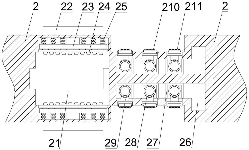
[0042] Such as Figure 1-7 As shown, on the basis of Embodiment 1, the present invention provides a technical solution: preferably, a docking door frame is provided on one side of the outer surface of the movable and closed protective glass door 2, and a docking groove is provided on the outer surface of the docking door frame 21. The surface of the moving and closing protective glass door 2 is provided with a snap groove b1, and the outer surface of the snap groove b1 is provided with a protective glass b2, and the outer surface of the protective glass b2 is provided with a reinforced glass filament b3, and the butt joint groove 21 A pusher 22 is detachably installed on the outer surfaces of the upper and lower sides, and a push plate 23 is detachably connected to the output end of the pusher 22, and a trapezoidal extruded soft block is detachably connected to the outer surface of one side of the push plate 23 24. The outer surface of one side of the push plate 23 is provided...

Embodiment 3

[0045] Such as Figure 1-7 Shown, on the basis of embodiment 1, the present invention provides a kind of technical proposal: preferably, on the inner surface of both sides of the waste material cooling device 1, the waste material insulation board 11 is detachably connected, and the outer surface of the waste material insulation board 11 A gas-permeable layer 12 is provided, and the lower surface of the gas-permeable layer 12 is lapped with an air blowing head 13, and the top outer surface of the waste insulation plate 11 is detachably connected with a material guide inclined plate 14, and the right side of the waste cooling device 1 A rotator 15 is detachably installed on the outer surface of the side, and the output end of the rotator 15 is detachably connected with a rotating rod 16, and one end of the rotating rod 16 extends to the inner surface of the waste cooling device 1 and is movably overlapped on the guide swash plate On the outer surface of 14, an electromagnetic e...


PUM


Abstract

The invention discloses a protective cover structure used on machining equipment, and relates to the technical field of protective covers, the protective cover structure comprises a waste cooling device, a movable closed protective glass door, a locking button, a material processor, an air suction disc, a purification air guide pipe and a workbench, the workbench is arranged on the outer surface of the top of the waste cooling device, and the movable closed protective glass door is arranged on the workbench; a movable closing protective glass door is arranged on the outer surface of the workbench, and a locking button is arranged on the outer surface of the movable closing protective glass door. The exhaust fan is used for absorbing outside air, the exhaust fan is matched with the metal particle filter plate to filter the outside air, then the exhaust gas is guided into the purification liquid through the gas guide pipe to be purified, the exhaust gas is guided through the gas conveying pipe, the moisture filter layer is used for filtering moisture, and the exhaust gas purification device has the characteristic of purifying the exhaust gas; the problem that a traditional pipeline can only be used for transferring gas, and consequently the effect is single is solved, and the effect of purifying waste gas is achieved.

Description

technical field [0001] The invention relates to the technical field of protective covers, in particular to a protective cover structure used on machining equipment. Background technique [0002] The protection of large CNC lathes adopts a semi-closed form of protection, with single or double sliding doors, semi-closed end plates on both sides, and vertical plates on the back. There are following problems at prior art: [0003] 1. The protective cover of the existing canceling device adopts a single or double sliding door. When the sliding door is closed, it can only be closed simply. After a long time of use, there will be a gap in the closed part. As a result, the sliding doors cannot be effectively closed, and the debris and harmful gases generated during internal processing will float out; [0004] 2. Turning is to use extrusion and friction to scrape off the debris from the surface of the material. In the process of scraping, the surface of the debris will produce vari...

Claims


Application Information

Patent Timeline
Patent Type & Authority Applications(China)
IPC IPC(8): B23Q11/08B23Q11/00
CPCB23Q11/08B23Q11/00B23Q11/0042
Inventor 闻琦
Owner 湖州天祺自动化科技有限公司
Why Eureka
Try Eureka