Die clamping mechanism of die-casting machine and die-casting machine
A die-casting machine and die-locking technology, applied in the field of die-locking mechanisms and die-casting machines, can solve the problems of overloading and damage of tie rods.
- Summary
- Abstract
- Description
- Claims
- Application Information
AI Technical Summary
Problems solved by technology
Method used
Image
Examples
Embodiment 1
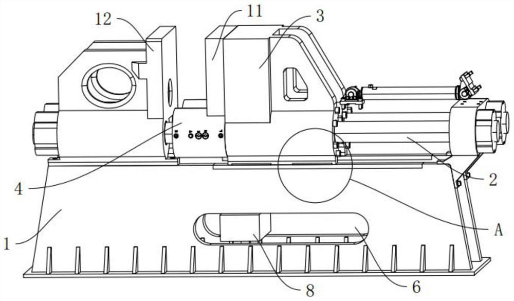
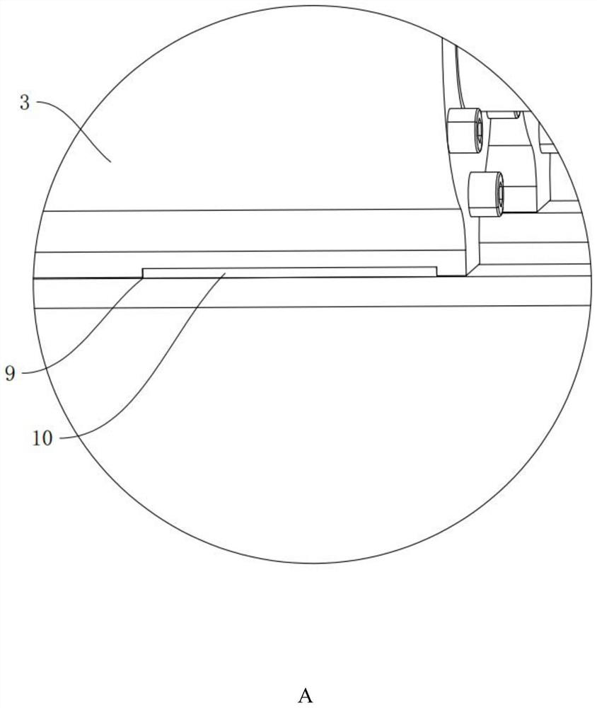
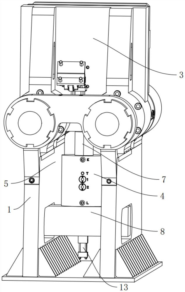
[0037] refer to Figure 1-Figure 5 As shown, the present invention provides a mold locking mechanism of a die casting machine, comprising a main frame 1, a mold locking base 3 and a locking assembly 4, the main frame 1 is provided with a sliding rod 2, and the sliding rod 2 is arranged horizontally; the mold locking The seat 3 passes through the sliding rod 2 and is slidably arranged on the sliding rod 2, the movable template 11 is arranged on the clamping seat 3; the locking assembly 4 is arranged on the said clamping seat 3, and the sliding rod 2 passes through the locking Component 4, the locking component 4 slides on the sliding rod 2 along with the clamping base 3, when the clamping base 3 is locked, the locking component 4 and the side wall of the sliding rod 2 are frictionally tight, limiting the lock Changes in the relative positions of the tight assembly 4 and the sliding rod 2.
[0038] There are two groups of the locking assembly 4 and the sliding rod 2 , and the t...
Embodiment 2
[0046] refer to Figure 1-5 As shown, the present invention provides a die-casting machine, including a die-locking mechanism of the die-casting machine, and a fixed die plate 12 arranged on the main frame 1, the fixed die plate 12 and the movable die plate 11 are arranged correspondingly, and the movable die plate 11 faces Move close to or away from the fixed plate 12. When locking the clamping base 3, the locking assembly 4 and the side wall of the sliding rod 2 are frictionally pressed against each other, limiting the change of the relative position of the locking assembly 4 and the sliding rod 2. When When in use, the movable template 11 on the clamping base 3 slides directly on the sliding rod 2 under the drive of the rear oil cylinder, thereby driving the clamping base 3 to move, thereby adjusting the position of the movable template 11. During the molding process, the locking assembly 4 is started at this time, and the locking assembly 4 starts to work, so that the lock...
PUM
 Abstract
Description
Claims
Application Information
 - Generate Ideas
- Intellectual Property
- Life Sciences
- Materials
- Tech Scout
- Unparalleled Data Quality
- Higher Quality Content
- 60% Fewer Hallucinations
Browse by: Latest US Patents, China's latest patents, Technical Efficacy Thesaurus, Application Domain, Technology Topic, Popular Technical Reports.
© 2025 PatSnap. All rights reserved.Legal|Privacy policy|Modern Slavery Act Transparency Statement|Sitemap|About US| Contact US: help@patsnap.com


