
Intelligent defect detection equipment for packaged chip

A technology of intelligent detection and defect detection, applied in sorting and other directions, which can solve problems such as pin deformation, lack of chip pin detection, and unfavorable installation processing.

Pending Publication Date: 2022-04-29
徐州盛科半导体科技有限公司
View PDF10 Cites 3 Cited by
  • Summary
  • Abstract
  • Description
  • Claims
  • Application Information

AI Technical Summary

Problems solved by technology

[0004] The purpose of the present invention is to provide a defect intelligent detection device for packaged chips, which solves the problem that the existing detection equipment often detects the chip body, and the pins of the packaged chip are designed in an external way, which is easy to be used during production, processing and transportation. During the process, the pins are deformed, which is not conducive to the subsequent installation process. The existing detection equipment lacks the way to detect the chip pins. This technical problem

Method used


Image

  • Intelligent defect detection equipment for packaged chip
  • Intelligent defect detection equipment for packaged chip
  • Intelligent defect detection equipment for packaged chip

Examples


Embodiment 1

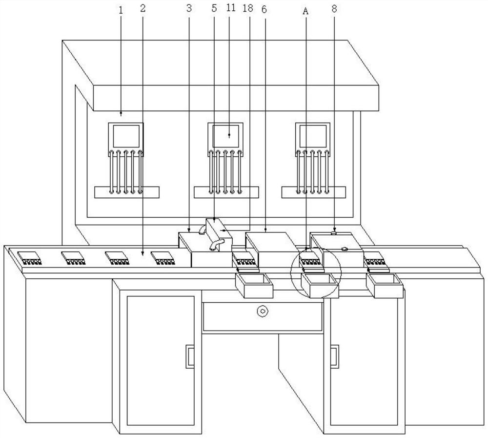
[0024] Example 1: See Figure 1-6 , the present invention provides a technical solution: a defect intelligent detection device for packaged chips, including a chip lead defect detection device, the chip lead defect detection device mainly includes an operation table 1, a conveyor 2, a lead shape detector, a lead Foot electrification detector, appearance image detector and rejecting mechanism, conveyor 2 is installed on console 1, pin shape detector is installed on console 1 and directly above conveyor 2, pin shape detector It is composed of a body casing 3, a lead corner detector 4 and a sprayer 5. The lead corner detector 4 is divided into two groups and is symmetrically installed inside the body casing 3. The sprayer 5 is located on the back of the body casing 3. The pin electrification detector is installed on the right side of the pin shape detector and includes two sets of circuit detection splints 7 slidingly arranged on the inner wall of the body shell II 6, and the app...

Embodiment 2

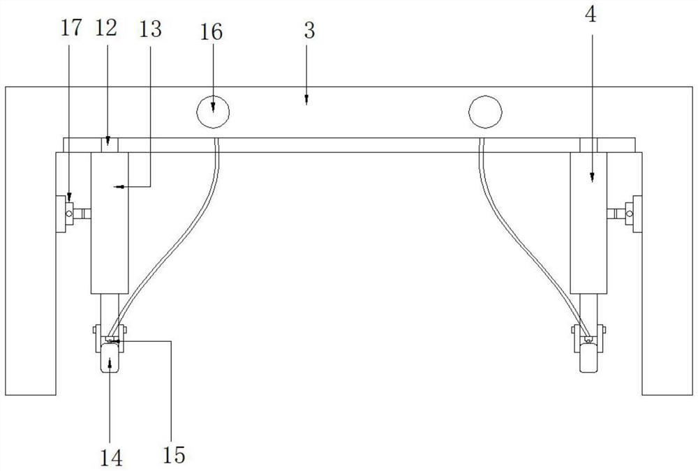
[0025] Embodiment 2: as figure 2 As shown: the pin corner detector 4 is composed of a slider 12, a telescopic rod 13, a corner detection wheel 14, a pressure sensor 15, an indicator light 16 and an electric push rod-17, and the slider 12 is slidably arranged on the inner wall of the body shell-3 The upper and lower ends are fixedly connected with the telescopic rod 13. The telescopic rod 13 has a two-stage structure and the corner detection wheel 14 is installed at the lower end. Connected, the indicator light 16 is installed on the front side of the body shell-3, the electric push rod-17 is installed on the side wall of the body shell-3 and the power output end is connected with the telescopic rod 13, and the electric push rod-17 promotes the telescopic rod 13 to move and make the corner detection wheel 14 corresponding to and in contact with the corner position of the pin, the pressure sensor 15 detects the pressure of the corner detection wheel 14, when the pressure value ...

Embodiment 3

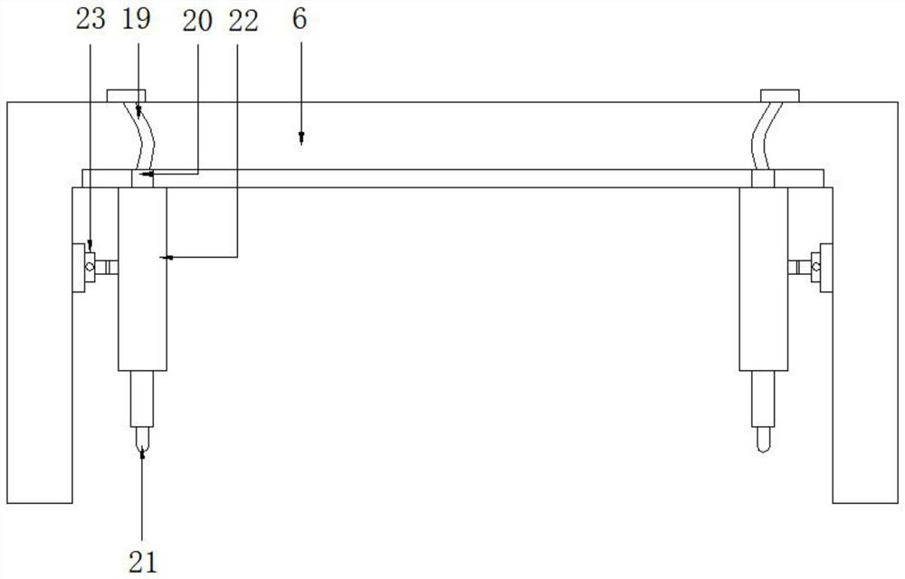
[0027] Embodiment 3: as image 3Shown: the sprayer 5 comprises the accommodation box 18 that is installed on the body shell one 3 and two groups of infusion tubes 19 that are connected with the accommodation box 18 through pipelines, the lower ends of the two groups of infusion tubes 19 are equipped with pumps 20, and the pumps 20 pass through The infusion tube 19 is connected with a spray head 21, the upper end of the spray head 21 is equipped with a vertical rod 22, the vertical rod 22 is slidably arranged on the inner wall of the body shell one 3 and one side is connected with an electric push rod two 23, and the pump 20 pumps the inside of the housing box 18 The marking solution is pumped to the nozzle 21, and sprayed on the corresponding pins through the nozzle 21, so as to facilitate the corresponding processing of the subsequent pins.


PUM


Abstract

The invention discloses a packaged chip defect intelligent detection device, which comprises a chip pin defect detection device, the chip pin defect detection device mainly comprises an operation table, a transmission machine, a pin form detector, a pin power-on detector, an appearance image detector and a defective product rejection mechanism, the transmission machine is installed on the operation table, and the transmission machine is installed on the operation table. The pin shape detectors are installed on the operation table and located over the conveyor, each pin shape detector is composed of a first machine body shell, two pin corner detectors and a sprayer, the two pin corner detectors are symmetrically installed in the first machine body shell, and the sprayers are located on the back face of the first machine body shell. According to the equipment specially designed for detecting the defects of the pins of the packaged chip, the detection equipment adopts an automatic conveying and three-stage detection mode, and the physical form, the power-on condition and the image information of the pins can be obtained.

Description

technical field [0001] The invention relates to the technical field of chip detection, in particular to an intelligent defect detection device for packaged chips. Background technique [0002] The shell used to install the semiconductor integrated circuit chip plays the role of placing, fixing, sealing, protecting the chip and enhancing the electrothermal performance, and it is also a bridge to communicate the internal world of the chip with the external circuit - the contacts on the chip are connected to the packaging shell with wires On the pins, these pins are connected to other devices through the wires on the printed board. Therefore, packaging plays an important role for CPU and other LSI integrated circuits. In order to ensure the product quality of the packaged chip, it is usually necessary to test the chip to ensure the quality of the finished product. [0003] However, there are the following problems in the existing testing process for packaged chips: (1) The exi...

Claims


Application Information

Patent Timeline
Patent Type & Authority Applications(China)
IPC IPC(8): B07C5/00B07C5/34B07C5/344B07C5/02B07C5/36
CPCB07C5/00B07C5/34B07C5/344B07C5/02B07C5/362
Inventor 吴龙军
Owner 徐州盛科半导体科技有限公司
Learn More