Device and method for detecting short-circuit fault point of finished printed circuit board
A printed circuit board and short-circuit fault technology, which is applied in the field of short-circuit fault point detection devices for finished printed circuit boards, can solve the problems of low detection efficiency of overlay detection and influence on the accuracy of detection results, so as to avoid low detection efficiency and improve efficiency. sex, the effect of increasing accuracy
- Summary
- Abstract
- Description
- Claims
- Application Information
AI Technical Summary
Problems solved by technology
Method used
Image
Examples
Embodiment 1
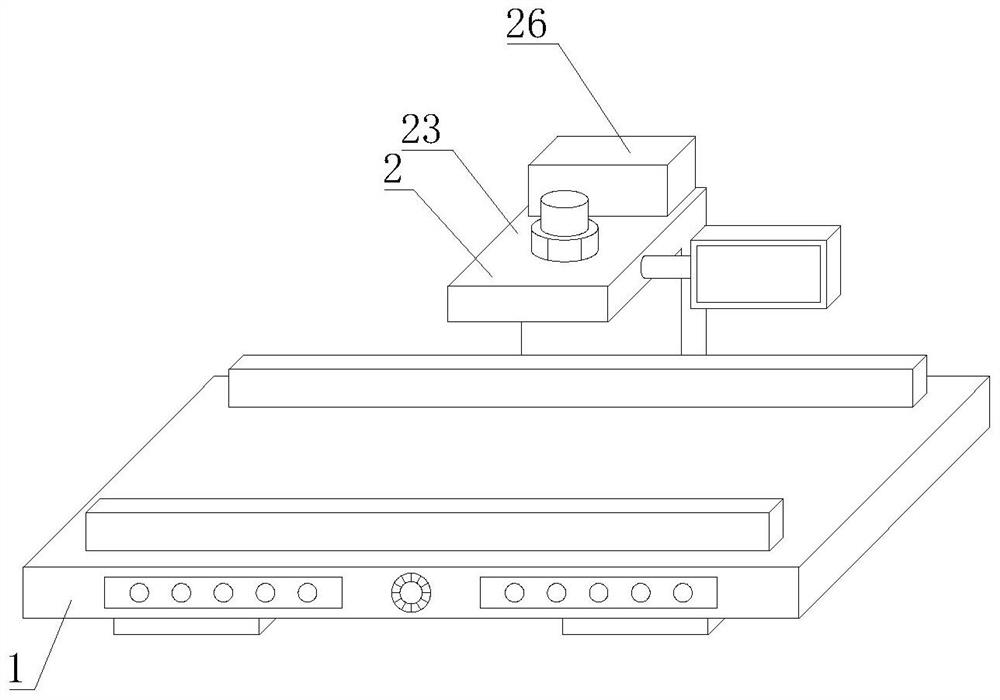
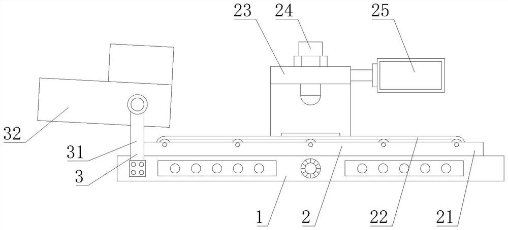
[0044] The first aspect, such as Figure 1-10 As shown, the present invention provides a finished printed circuit board short circuit fault point detection device, comprising a detection table 1, the top of the detection table 1 is provided with a continuous rapid positioning mechanism 2, the left side of the detection table 1 is provided with a pretreatment mechanism 3, the continuous fast positioning mechanism 2 includes a raised frame 21 and a turning frame 23, the raised frame 21 is fixed and welded on the top of the detection table 1, the inside of the raised frame 21 is provided with a conveyor belt 22, the folding frame 23 is fixed on the back of the testing table 1, The top of the folding frame 23 is fixed with a thermal imager body 24, the right side of the folding frame 23 is fixed with a display 25, the top of the folding frame 23 is provided with a background temperature compensation mechanism 26, the pretreatment mechanism 3 includes a lift 31, the lift 31 is fixed on ...
Embodiment 2
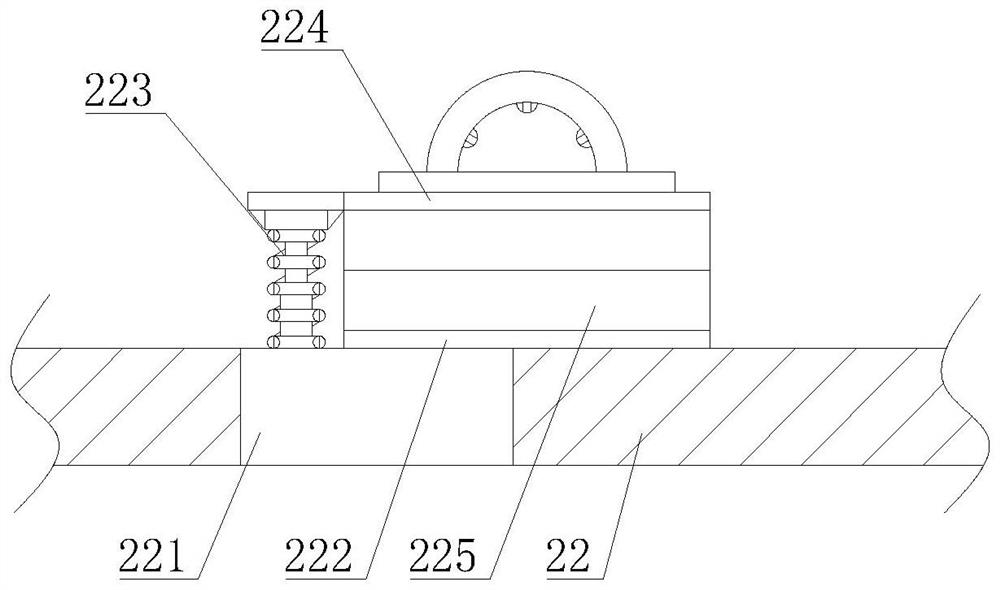
[0046] as Figure 1-10 As shown, on the basis of Example 1, the present invention provides a technical solution: preferably, the top of the conveyor belt 22 is fixed mounted with an embedding block 221, the top of the embedding block 221 is fixed welded with a fixed substrate 222, the top of the embedding block 221 is fixed with an elastic card member 223, the top of the elastic card piece 223 is fixed welded with a movable substrate 224, the fixed substrate 222, the adjacent side of the movable substrate 224 is provided with a buffer protection mechanism 225, Buffer protection mechanism 225 includes a sponge pad 2251, two sponge pads 2251 are fixed to the adjacent side of the fixed substrate 222 and the movable substrate 224, the adjacent side of the two sponge pads 2251 are fixed connected to the airbag pad 2252, the adjacent side of the two airbag pads 2252 are fixed to the insulating silicone pad 2253, the adjacent side of the two insulating silicone pads 2253 are fixed to the ...
Embodiment 3
[0048] as Figure 1-10As shown, on the basis of Example 1, the present invention provides a technical solution: preferably, the left side of the protective cover 33 is disassembled with a filter cartridge 37, the outlet pipe of the suction pump 34 is connected to the top of the filter cartridge 37 actively connected, the inner chamber of the filter cartridge 37 is fixed with the inner ring 371, the bottom of the inner ring 371 is disassembled with a coarse filter cotton cover 372, the bottom thread of the filter cartridge 37 is connected to the PP cotton filter cartridge 373, the top of the filter cartridge 37 is fixed with a unidirectional obstruction pipe 374, The interior of the unidirectional obstruction pipe 374 is opened with a one-way inner groove 3741, the bottom of the unidirectional inner groove 3741 is provided with elastic feet 3742, the top of the elastic foot 3742 is fixed with a rubber jacket 3744, the rubber jacket 3744 is fixed on the inner wall of the closed ball...
PUM
 Abstract
Description
Claims
Application Information
 - R&D
- Intellectual Property
- Life Sciences
- Materials
- Tech Scout
- Unparalleled Data Quality
- Higher Quality Content
- 60% Fewer Hallucinations
Browse by: Latest US Patents, China's latest patents, Technical Efficacy Thesaurus, Application Domain, Technology Topic, Popular Technical Reports.
© 2025 PatSnap. All rights reserved.Legal|Privacy policy|Modern Slavery Act Transparency Statement|Sitemap|About US| Contact US: help@patsnap.com


