
Novel brake caliper body structure

A caliper body and a new type of technology, applied in the field of brake calipers, can solve the problems of increasing the process of connecting plate processing, high processing accuracy requirements, unreliable caliper body connection, etc., to reduce processing procedures, good sealing effect, and eliminate caliper The effect on the risk of body oil spills

Pending Publication Date: 2022-04-26
XINXIANG KEGONG IND
View PDF1 Cites 0 Cited by
  • Summary
  • Abstract
  • Description
  • Claims
  • Application Information

AI Technical Summary

Problems solved by technology

[0002] The brake caliper body is composed of a left caliper body and a right caliper body. The left caliper body and the right caliper body are connected by bolts. Only relying on the bolt connection leads to unreliable connection of the caliper body and low strength. There will be an outward tension when moving, and oil leakage is likely to occur due to insufficient strength. In the patent application number CN110067825A, a connection structure of a brake caliper is disclosed, including a left caliper, a right caliper and a left and right caliper. The brake disc set between the left and right caliper bodies is connected by a connecting plate, and the connecting plate is provided with a through hole matched with the connecting bolt, and the bolts pass through the left caliper body, connecting plate and right caliper body successively to connect the three The latter is fastened and connected, but at the same time as the connecting plate is added, there is also an additional mating surface with the pliers, and it is mainly fixed by bolts, resulting in unreliable structure, increasing the process of connecting plate processing, and requiring higher processing accuracy. , can not solve the problem of oil leakage, the existing structure of the brake caliper cannot meet the needs of actual use, so the market urgently needs improved technology to solve the above problems

Method used


Image

  • Novel brake caliper body structure
  • Novel brake caliper body structure
  • Novel brake caliper body structure

Examples


Embodiment 1

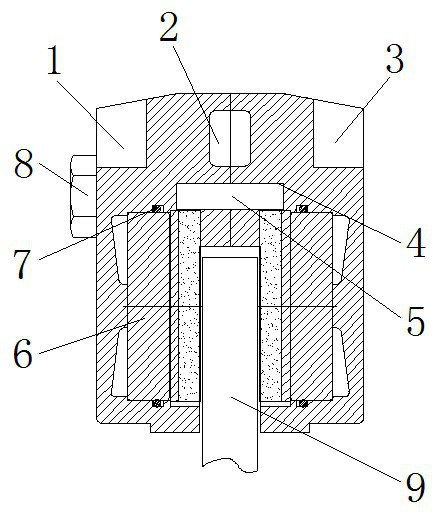
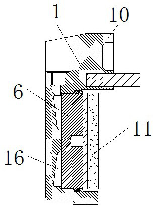
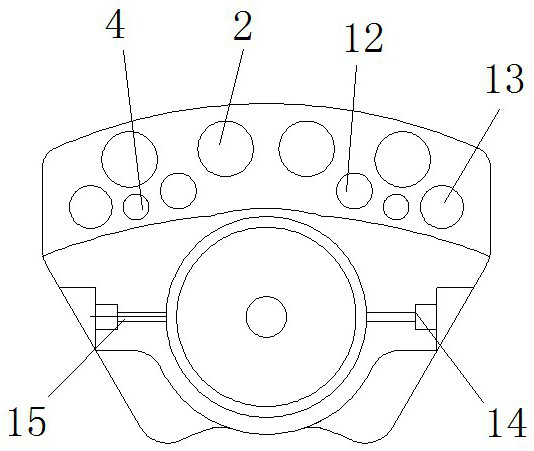
[0020] see Figure 1-3 , the present invention provides a technical solution: a novel brake caliper body structure, including a left caliper body 1, a right caliper body 3 and a brake disc 9, and the mating surfaces of the left caliper body 1 and the right caliper body 3 are provided with matching The raised part 10 and the brake disc 9 are arranged below the matching raised part 10 between the left caliper body 1 and the right pliers body 3, and the matching raised part 10 is provided with a cooling hole 2, and the heat dissipation area is increased through the cooling hole 2, The volatilization of heat during braking can be accelerated. A positioning column 5 is arranged between the matching raised parts 10, and a positioning hole 4 is arranged on the matching raised part 10. The positioning hole 4 is arranged on one side of the connecting hole 13, and the two positioning posts 5 The end and the positioning hole 4 are connected by interference fit. The positioning hole 4 is ...


PUM


Abstract

The invention discloses a novel brake caliper body structure which comprises a left caliper body, a right caliper body and a brake disc, matching protruding parts are arranged on the matching faces of the left caliper body and the right caliper body, the brake disc is arranged below the matching protruding parts between the left caliper body and the right caliper body, and a positioning column is arranged between the matching protruding parts. Connecting holes are formed in the two sides of the matched protruding part of the left clamp body and the two sides of the matched protruding part of the right clamp body, the connecting hole in the left clamp body is connected with the connecting hole in the right clamp body through a connecting bolt, a positioning hole is formed in the matched protruding part, and the positioning hole is formed in one side of the connecting hole. The two ends of the positioning column are connected with the positioning holes in an interference fit mode, the positioning column is conveniently connected and positioned through the positioning holes, and the left clamp body and the right clamp body are reliably connected together through the positioning column. The clamp is novel in structural design and convenient to install, matched positioning between the clamp bodies is facilitated, the strength between the clamp body matching faces is improved, and the risk of oil leakage of the clamp bodies is eradicated.

Description

technical field [0001] The invention relates to the technical field of brake caliper, in particular to a novel brake caliper body structure. Background technique [0002] The brake caliper body is composed of a left caliper body and a right caliper body. The left caliper body and the right caliper body are connected by bolts. Only relying on the bolt connection leads to unreliable connection of the caliper body and low strength. There will be an outward tension when moving, and oil leakage is likely to occur due to insufficient strength. In the patent application number CN110067825A, a connection structure of a brake caliper is disclosed, including a left caliper, a right caliper and a left and right caliper. The brake disc set between the left and right caliper bodies is connected by a connecting plate, and the connecting plate is provided with a through hole matched with the connecting bolt, and the bolts pass through the left caliper body, connecting plate and right calip...

Claims


Application Information

Patent Timeline
Patent Type & Authority Applications(China)
IPC IPC(8): F16D65/092F16D65/14F16D65/847F16D121/04
CPCF16D65/092F16D65/14F16D65/847F16D2121/04
Inventor 杜长文
Owner XINXIANG KEGONG IND
Learn More