Road and bridge marking device
A scribing device and road technology, applied in roads, roads, road repairs, etc., can solve problems affecting the speed of scribing, achieve good adhesion, improve work efficiency, and have a long service life
- Summary
- Abstract
- Description
- Claims
- Application Information
AI Technical Summary
Problems solved by technology
Method used
Image
Examples
Embodiment 1
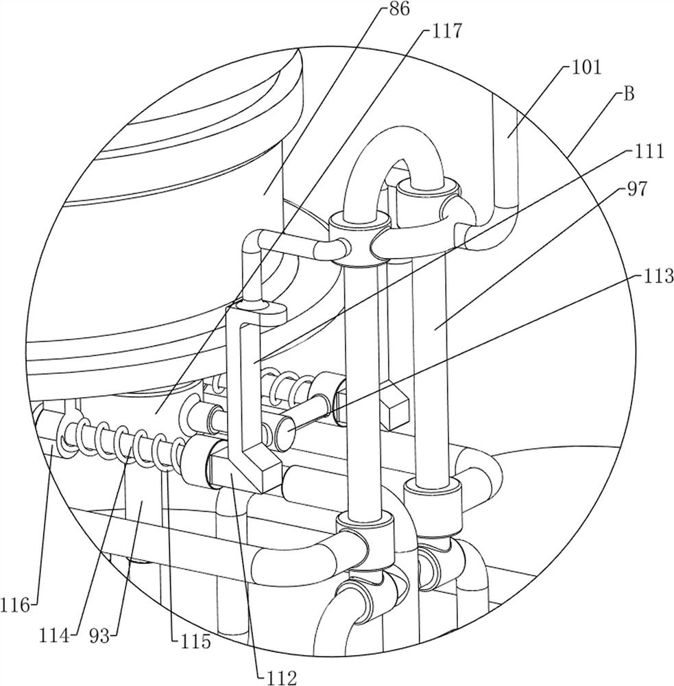
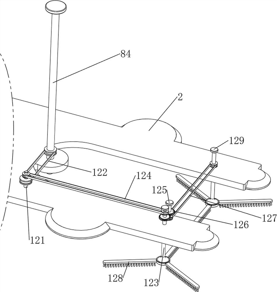
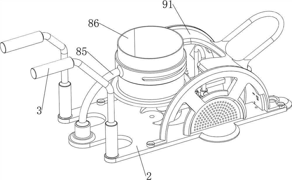
[0038] A road bridge marking device, with reference to Figure 1-9 , including a tire 1, a bottom plate 2, a push rod 3, a fixed plate 4, a collection frame 5, a first slide bar 6, a first linear spring 7, a stirring mechanism 8 and a marking mechanism 9, the left and right sides of the bottom of the bottom plate 2 are The rotary type is provided with a tire 1, the front and rear sides of the top left side of the base plate 2 are provided with push rods 3, the right side of the base plate 2 is fixedly connected with a fixed plate 4 by bolts, and the fixed plate 4 is slidingly provided with four first slide bars 6. There is a collection frame 5 between the right side of the first slide bar 6. The collection frame 5 is used to collect and push away garbage. There are four first linear springs 7 connected between the fixed plate 4 and the collection frame 5. The first The linear springs 7 are all set on the first slide bar 6 on the same side, and the top left side of the bottom p...
Embodiment 2
[0043] On the basis of embodiment 1, refer to figure 1 and Figure 10 , also includes a pressing mechanism 10, and the pressing mechanism 10 includes a driving rod 101, a second linear spring 102, a fourth fixed column 103, a limit ring 104, a third linear spring 105, an arc plate 106 and a rotating rod 107 , the upper part of the first pressure rod 97 is provided with a driving rod 101, and the two sides of the front side of the bottom of the driving rod 101 are connected with the two third fixed columns 92 on the same side with a second linear spring 102, and the second linear springs 102 are evenly set. On the first pressing rod 97, the right side of the top of the cover plate 88 is provided with a fourth fixed column 103, the upper part of the fourth fixed column 103 is slidably provided with a limit ring 104, and the left side of the limit ring 104 is provided with an arc-shaped plate 106. A third linear spring 105 is connected between the right side of the shaped plate ...
PUM
 Abstract
Description
Claims
Application Information
 - R&D Engineer
- R&D Manager
- IP Professional
- Industry Leading Data Capabilities
- Powerful AI technology
- Patent DNA Extraction
Browse by: Latest US Patents, China's latest patents, Technical Efficacy Thesaurus, Application Domain, Technology Topic, Popular Technical Reports.
© 2024 PatSnap. All rights reserved.Legal|Privacy policy|Modern Slavery Act Transparency Statement|Sitemap|About US| Contact US: help@patsnap.com


