
Pressure detection device for track inspection robot and track inspection robot

A technology of inspection robots and detection devices, applied in the field of robots

Active Publication Date: 2022-04-26
HANGZHOU SHENHAO TECH
View PDF9 Cites 0 Cited by
  • Summary
  • Abstract
  • Description
  • Claims
  • Application Information

AI Technical Summary

Problems solved by technology

However, the existing track measuring instruments and track inspection instruments cannot perform fine detection of defect damage, material degradation, and local deformation of the rail caused by corrosion.

Method used


Image

  • Pressure detection device for track inspection robot and track inspection robot
  • Pressure detection device for track inspection robot and track inspection robot
  • Pressure detection device for track inspection robot and track inspection robot

Examples


Embodiment 1

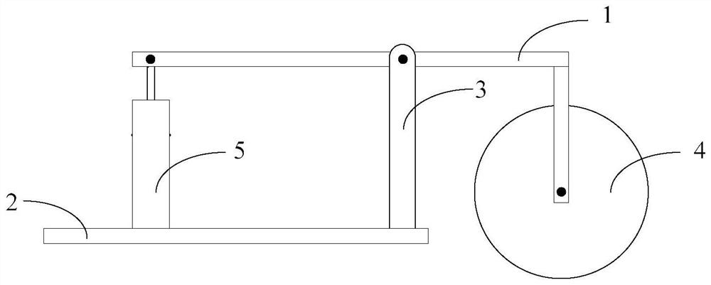
[0036] figure 1 It is a schematic structural diagram of a pressure detection device for a track inspection robot in an embodiment of the present application. like figure 1 As shown, the pressure detection device for the track inspection robot in this embodiment includes: a first support arm 1, a second support arm 2, and a first connecting rod 3;

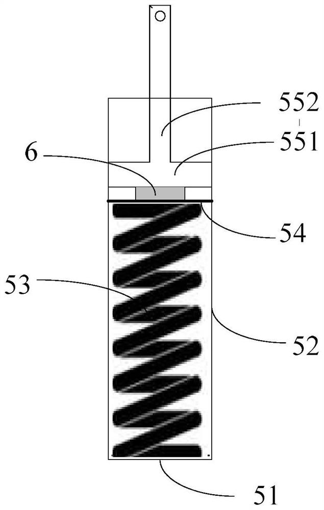
[0037] One end of the first support arm 1 is equipped with a detection wheel 4, and the other end is provided with an elastic compression assembly 5. The first support arm 1 is rotatably connected with the elastic compression assembly 5. A pressure sensor 6 is arranged in the elastic compression assembly 5. The first support The middle part of the arm 1 is rotatably connected to one end of the first connecting rod 3; the detection wheel 4 can rotate and walk on one side of the rail surface or the rail waist;

[0038] One end of the second support arm 2 is vertically and fixedly connected to the other end of the connecting rod 3 , ...

Embodiment 2

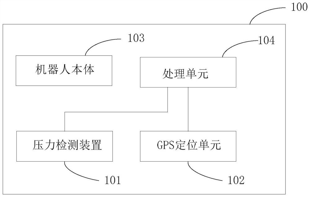
[0049] The second aspect of the present application provides a track inspection robot 100, image 3 It is a schematic structural diagram of the track inspection robot in another embodiment of the present application, such as image 3 As shown, the track inspection robot 100 includes: at least one pressure detection device 101 as described in any one of the first aspect above, and a robot body 103 capable of traveling on at least one rail, a positioning unit 102, and a processing unit 104;

[0050] The pressure detection device 101 is arranged on the robot body 103, and is used to detect the pressure exerted by the detection wheel of the rail inspection robot 100 on the surface or the rail waist of the rail to be detected when walking on the surface or the rail waist;

[0051] The positioning unit 102 is arranged on the robot body 100 and is connected with the processing unit 104, and is used to collect the coordinate information of the current position in real time, and send t...


PUM


Abstract

The invention relates to a pressure detection device for a track inspection robot. The device comprises a first supporting arm, a second supporting arm and a first connecting rod, a detection wheel is installed at one end of the first supporting arm, an elastic compression assembly is arranged at the other end of the first supporting arm, the first supporting arm is rotationally connected with the elastic compression assembly, a pressure sensor is arranged in the elastic compression assembly, and the middle of the first supporting arm is rotationally connected with one end of the first connecting rod; the detection wheel can rotate and walk on the surface or the rail web of a steel rail on one side; one end of the second supporting arm is perpendicularly and fixedly connected with the other end of the connecting rod, the other end of the second supporting arm is fixedly connected with the track inspection robot, and the middle of the second supporting arm is fixedly connected with the elastic compression assembly. The pressure detection device provided by the invention can accurately detect the wheel pressure change caused by the local deformation of the steel rail due to rail defect damage, material degradation and corrosion, thereby realizing the fine detection of the local deformation of the steel rail.

Description

technical field [0001] The application belongs to the technical field of robots, and in particular relates to a pressure detection device for a track inspection robot and a track inspection robot. Background technique [0002] The rapid development of high-speed railways in my country has brought challenges to the state maintenance and safety assurance of railway infrastructure. Steel rails are the main components of railway tracks and directly bear the pressure from wheel sets. Defects, damage and material degradation during long-term use affect other components. Service performance and threats to traffic safety. Rail deformation and corrosion caused by rail stress, fatigue and defects will lead to major accidents such as train derailment and overturning, which will cause casualties and huge property losses. With the increase of high-speed rail traffic density and speed , the load of the rail and the degree of extrusion and impact, the probability of rail failure and damage i...

Claims


Application Information

Patent Timeline
Patent Type & Authority Applications(China)
IPC IPC(8): B61K9/08B61D15/12
CPCB61K9/08B61D15/12
Inventor 汪春叶德辉邓成呈吴雅婷
Owner HANGZHOU SHENHAO TECH
Learn More