
Valve device

A valve device and valve seat technology, applied in valve device, valve operation/release device, valve details, etc., can solve the problems of low efficiency, high cost, complicated process, etc., to simplify the production process, improve production efficiency, stamping simple craftsmanship

Pending Publication Date: 2022-04-22
ZHEJIANG SANHUA INTELLIGENT CONTROLS CO LTD
View PDF0 Cites 1 Cited by
  • Summary
  • Abstract
  • Description
  • Claims
  • Application Information

AI Technical Summary

Problems solved by technology

[0004] The valve seat of the electric valve is usually composed of a first plate member and a second plate member, wherein the first plate member is a stamping part, and the second plate member is a turning part. Since the second plate member is a turning part, the process is complicated. , low efficiency and high cost

Method used


Image

  • Valve device
  • Valve device
  • Valve device

Examples


Embodiment Construction

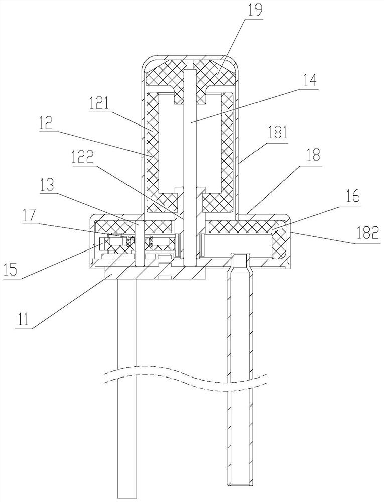
[0027] In order to enable those skilled in the art to better understand the solution of the present invention, the present invention will be further described in detail below in conjunction with the accompanying drawings and specific embodiments.

[0028] In this article, terms such as "upper, lower, left, right" are established based on the positional relationship shown in the drawings, and the corresponding positional relationship may also change accordingly depending on the drawings. It is understood as an absolute limitation on the scope of protection; moreover, relative terms such as "first" and "second" are only used to distinguish one from another component with the same name, and do not necessarily require or No such actual relationship or order between these components is implied.

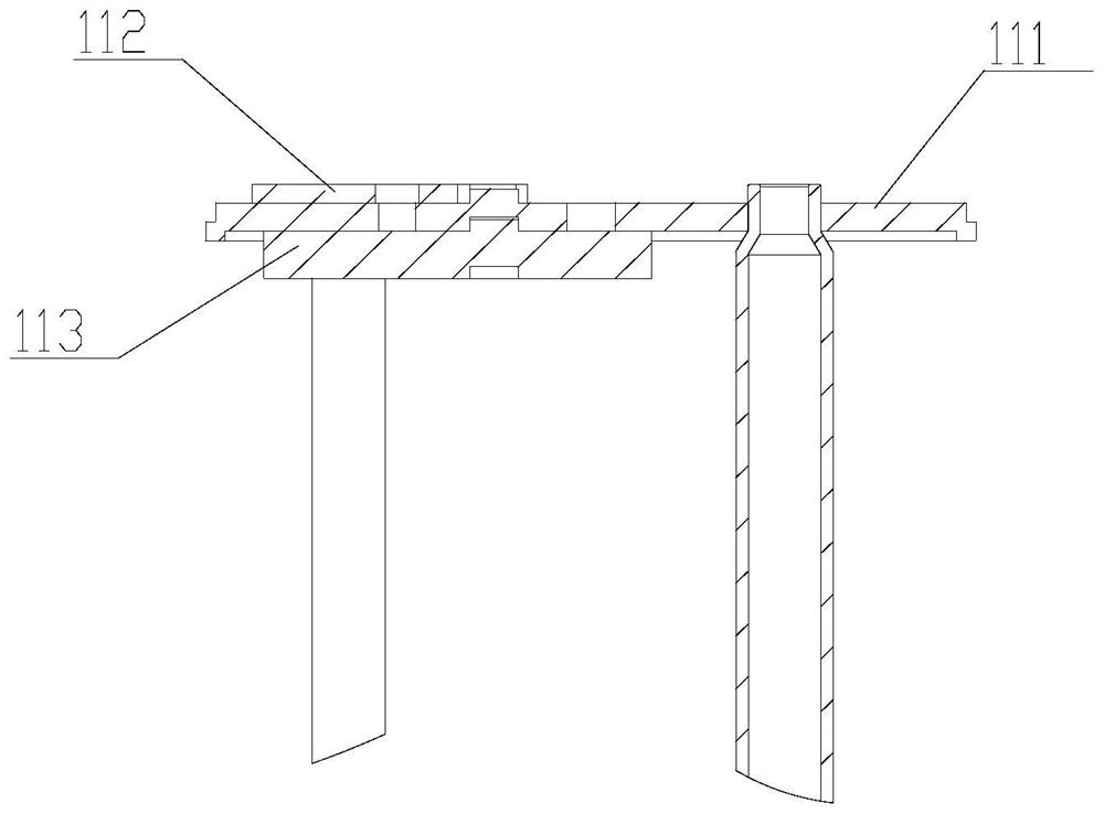
[0029] Please refer to figure 1 , figure 2 , image 3 , figure 1 It is a cross-sectional view of a valve device disclosed in an embodiment of the present invention; figure 2 for fi...


PUM


Abstract

The valve device comprises a valve body, a valve seat, a rotor component and an adjusting component, wherein the rotor component and the adjusting component are arranged in the valve body; the outer portion of the valve seat is connected with an inlet pipe and an outlet pipe, a sealing face matched with the adjusting component is arranged in the valve seat, and the sealing face is provided with a valve port. The rotor part is in transmission connection with the adjusting part so as to drive the adjusting part to rotate; the adjusting component controls the communicating state of the valve port and the inlet pipe by rotating to different working positions on the sealing face, the valve seat comprises at least two layers of flat plates which are stacked and connected in a welded mode, and each layer of flat plate is a stamping part. The valve device is simple in manufacturing process and high in production efficiency.

Description

technical field [0001] The invention relates to the technical field of control valves, in particular to electric control valves. Background technique [0002] In a traditional refrigerating system, such as a refrigerator refrigerating system, the control components for refrigerant flow are mostly two-position three-way solenoid valves or bistable solenoid valves. These two kinds of valve driving signals are AC signals, so the interference is large and the power consumption is large. Sometimes the interference signal generated by the AC power of the power grid will cause the valve to malfunction. [0003] In this regard, more and more electric switching valves are used in refrigerator refrigeration systems. This type of control valve uses the principle of stepping motors to drive the rotor parts to rotate with coils, thereby driving the sliders to rotate, and controlling the communication between the inlet and multiple outlets. The disconnection relationship, reliable contro...

Claims


Application Information

Patent Timeline
Patent Type & Authority Applications(China)
IPC IPC(8): F16K11/074F16K3/30F16K31/04
CPCF16K11/0743F16K3/30F16K31/043
Inventor 不公告发明人
Owner ZHEJIANG SANHUA INTELLIGENT CONTROLS CO LTD
Learn More