Tower crane attachment frame
A technology for attaching frames and tower cranes, which is applied in the connection of poles, connecting components, cranes, etc., and can solve the problems of single and unadjustable attachment frames.
- Summary
- Abstract
- Description
- Claims
- Application Information
AI Technical Summary
Problems solved by technology
Method used
Image
Examples
Embodiment 1
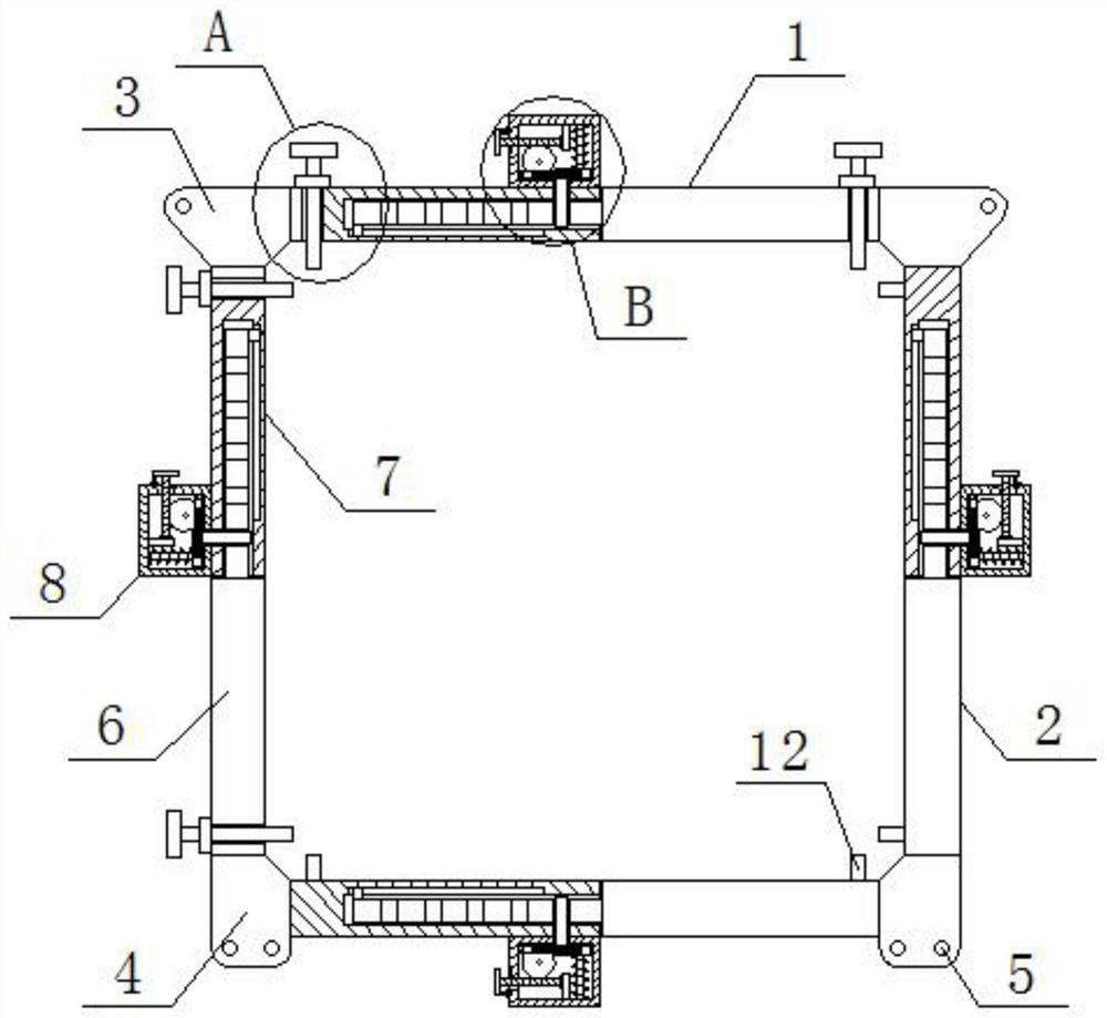
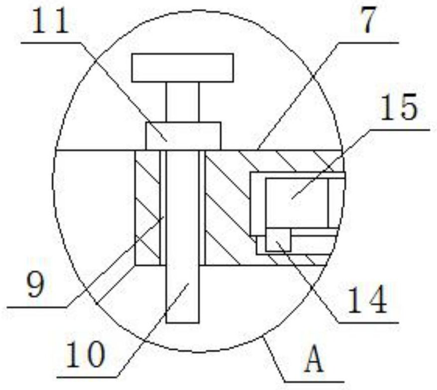
[0027] Reference Figure 1-9 , tower crane attachment frame, comprising a set of transverse adjustment components 1 and a set of longitudinal adjustment components 2, wherein the upper transverse adjustment assembly 1 and the two longitudinal adjustment components 2 are fixedly connected to a single-hole ear plate 3, the lower lateral adjustment assembly 1 and two longitudinal adjustment components 2 are fixedly connected to the double-hole ear plate 4, single-hole ear plate 3 and a double-hole ear plate 4 respectively opened with a pin hole 5 and two pin holes 5, the lateral adjustment assembly 1 and the longitudinal adjustment component 2 both include a square rod 6 and a square tube 7, Square tube 7 outer wall near the square rod 6 side fixed connection to the adjustment shell 8, the upper transverse adjustment assembly 1 and the left longitudinal adjustment assembly 2 are opened with two screw holes 9, screw hole 9 inner thread is installed with adjustment screw 10, adjustment ...
Embodiment 2
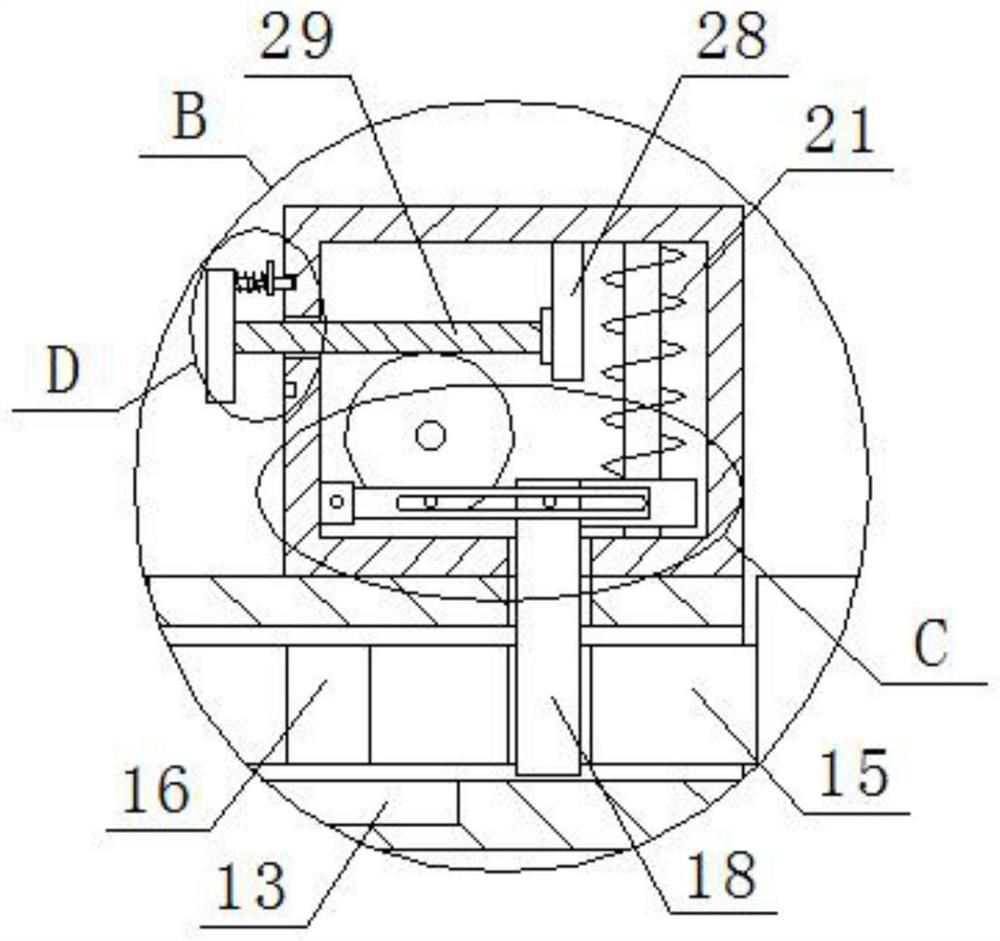
[0029] In the present invention, the waist groove rod 23 slide is mounted with no. 1 bump 24 and no. 25, and the no. 25 bump 25 is fixedly connected to the side of the latch 18, the no. 1 bump 25 rotates, can drive the waist slot rod 23 to rotate, and then drive the no. 2 brak 25 to move, and then drive the latch 18 to move.
[0030] In the present invention, the inner wall of the adjusting shell 8 is rotated to connect to one end of the straight rod 26, the other end of the straight rod 26 is provided with a worm gear 27, and the No. 1 bump 24 is fixedly connected to the side of the worm gear 27, the worm gear 27 rotates, can drive the No. 1 bump 24 to rotate.
[0031] In the present invention, the adjustment shell 8 is fixed to the inner wall of one side away from the square tube 7 is fixedly connected to the mounting block 28, the mounting block 28 is rotated from the side of the straight pipe 20 is connected to the worm 29.
[0032] In the present invention, the worm 29 is ext...
Embodiment 3
[0037] Reference Figure 1-9 , tower crane attachment frame, comprising a set of transverse adjustment components 1 and a set of longitudinal adjustment components 2, wherein the upper transverse adjustment assembly 1 and the two longitudinal adjustment components 2 are welded between a single-hole ear plate 3, the lower lateral adjustment assembly 1 and two longitudinal adjustment components 2 are welded between the double-hole ear plate 4, single-hole ear plate 3 and a double-hole ear plate 4 are chiseled on a pin hole 5 and two pin holes 5, the lateral adjustment assembly 1 and the longitudinal adjustment assembly 2 both include a square rod 6 and a square tube 7, Square tube 7 outer wall near the side of the square rod 6 welded with a control shell 8, the upper transverse adjustment assembly 1 and the left longitudinal adjustment assembly 2 are chiseled with two screw holes 9, screw hole 9 inner thread is installed with adjustment screw 10, adjustment screw 10 on the thread sle...
PUM
 Abstract
Description
Claims
Application Information
 - R&D Engineer
- R&D Manager
- IP Professional
- Industry Leading Data Capabilities
- Powerful AI technology
- Patent DNA Extraction
Browse by: Latest US Patents, China's latest patents, Technical Efficacy Thesaurus, Application Domain, Technology Topic, Popular Technical Reports.
© 2024 PatSnap. All rights reserved.Legal|Privacy policy|Modern Slavery Act Transparency Statement|Sitemap|About US| Contact US: help@patsnap.com


