Electromechanical equipment transportation device capable of preventing stress damage
A technology for electromechanical equipment and transportation devices, applied in the field of electromechanical equipment transportation devices for preventing stress damage, can solve the problems of adjusting the driving state of the vehicle, stress damage of the limit mechanism, and inability to remind the driver in time, so as to improve the practicability and hinder the The effect of shaking and improving the protective effect
- Summary
- Abstract
- Description
- Claims
- Application Information
AI Technical Summary
Problems solved by technology
Method used
Image
Examples
Embodiment 1
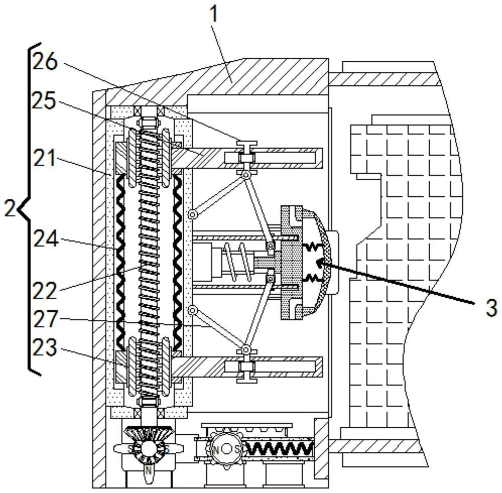
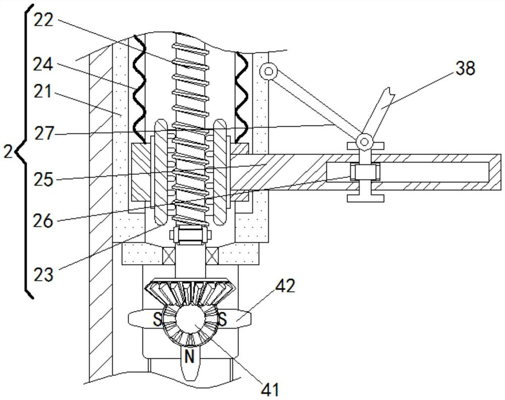
[0022] see figure 1 , 3 , 4. An electromechanical equipment transportation device for preventing stress damage, comprising a housing 1, the left wall of the inner cavity of the housing 1 is fixedly connected with an inertial mechanism 2, and the middle part of the inner cavity of the housing 1 is fixedly connected with an extension to the inertial mechanism 2 The limit mechanism 3, the bottom of the inner cavity of the housing 1 is fixedly connected with the early warning mechanism 4, the inertia mechanism 2 includes a positioning frame 21, a threaded gear rod 22, an adjustment frame 23, a limit spring 24, an extension plate 25, a slider 26, The strut 27 is fixedly connected with a positioning frame 21 on the left wall of the inner cavity of the housing 1, and the inner cavity of the positioning frame 21 is rotatably connected with a threaded toothed rod 22. The size of the threaded toothed rod 22 matches the size of the adjustment frame 23, and The two are meshed and connect...
Embodiment 2
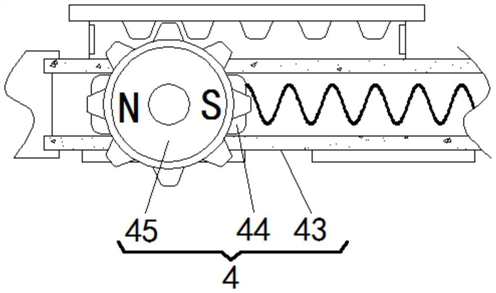
[0024] see figure 2 , 3, 4. An electromechanical equipment transportation device for preventing stress damage, comprising a housing 1, the left wall of the inner cavity of the housing 1 is fixedly connected with an inertial mechanism 2, and the middle part of the inner cavity of the housing 1 is fixedly connected with an extension to the inertial mechanism 2 The limit mechanism 3 of the housing 1 is fixedly connected with the early warning mechanism 4 at the bottom of the inner cavity of the housing 1. The early warning mechanism 4 includes a rotating gear 41, a magnetic gear 42, a winding frame 43, a movable block 44, and a rotating magnetic disk 45. The interior of the housing 1 The bottom of the chamber is rotatably connected with a rotating gear 41. The rotating gear 41 is located below the threaded gear rod 22 and meshed with it. The rear end of the rotating gear 41 is fixedly sleeved with a magnetic gear 42. The magnetic poles are opposite, and the two are relatively a...
Embodiment 3
[0026] see Figure 1-4 , a mechanical and electrical equipment transportation device for preventing stress damage, comprising a housing 1, the left wall of the inner cavity of the housing 1 is fixedly connected with an inertial mechanism 2, and the inertial mechanism 2 includes a positioning frame 21, a threaded gear rod 22, an adjusting frame 23, a limiter Position spring 24, extension plate 25, slide block 26, pole 27, the inner cavity left wall of housing 1 is fixedly connected with positioning frame 21, and the inner cavity of positioning frame 21 is connected with threaded toothed rod 22, and the threaded toothed rod 22 The size matches the size of the adjustment frame 23, and the two are meshed and connected. The top and bottom of the inner cavity of the positioning frame 21 are slidably connected with the adjustment frame 23 sleeved on the threaded gear rod 22. Between the adjustment frame 23 Fixedly connected with the limit spring 24, the right end of the adjustment fr...
PUM
 Abstract
Description
Claims
Application Information
 - R&D Engineer
- R&D Manager
- IP Professional
- Industry Leading Data Capabilities
- Powerful AI technology
- Patent DNA Extraction
Browse by: Latest US Patents, China's latest patents, Technical Efficacy Thesaurus, Application Domain, Technology Topic, Popular Technical Reports.
© 2024 PatSnap. All rights reserved.Legal|Privacy policy|Modern Slavery Act Transparency Statement|Sitemap|About US| Contact US: help@patsnap.com


