


Quick Research
Generate reliable direction feasibility study reports for your R&D in just a few steps.

Technical Q&A
Discover and master advanced knowledge NOW. Basics, ideas, possibilities, all at once.

Find Solutions
As an expert in R&D theories, this can generate solutions to your technical problems instantly.

Evaluate Feasibility
Analyze your overall solution with one click, know your potential R&D risks in advance.

Monitor Landscape
Get weekly tech updates, stay abreast of the latest tech innovations and key insights.
Converged communication terminal with optical fiber signal self-coding and self-decoding functions
A converged communication, encoding and decoding technology, applied in the field of converged communication terminals, can solve the problems of inconvenient plugging and unplugging connectors of converged communication terminals, loose and damaged electrical components of the circuit board, and failure of electrical components, so as to avoid internal moisture, vibration loosening or Damage, avoid wear effect
- Summary
- Abstract
- Description
- Claims
- Application Information
AI Technical Summary
Problems solved by technology
Method used
Image

Examples
Embodiment 1
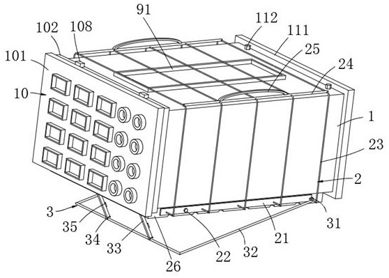
[0056] Example 1, please refer to Figure 1-11 , a converged communication terminal with its own encoding and decoding of optical fiber signals, including:
[0057] The installation box 1 is provided with openings at the front and rear ends respectively, the opening on the front side is equipped with a connection panel unit 11, and the opening on the rear side is equipped with a drying assembly 11;
[0058] The connection panel unit 10 includes a panel 101, an installation sleeve 102 and a quick release assembly. The rear side of the panel 101 is fixedly connected with an installation sleeve 102. Disassemble the assembly to connect the upper front end of the installation box 1. The installation sleeve 102 facilitates the installation of the panel 101, and at the same time, the quick fixation of the installation sleeve 102 can be completed through the quick release assembly.
[0059] The quick release assembly includes a groove 103, a through groove 104, a mounting shaft 105,...
Embodiment 2
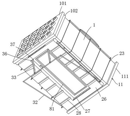
[0077] Example 2, please refer to Figure 1-2 , a converged communication terminal with its own encoding and decoding of optical fiber signals, the structure of this embodiment is roughly the same as that of Embodiment 1, the difference is that:
[0078] The inclined support unit 3 includes a movable seat 31, an arched support rod 32, a strut 33, an arc-shaped clamp rod 34, an adsorption magnetic block 35, a mounting seat 36 and a movable shaft 37, and the rear ends of the protection bottom frame 26 are respectively provided with There is a movable seat 31, and the two ends of the arched support rod 32 are movably connected with the two movable seats 31 respectively, and the front ends of both sides inside the protective bottom frame 26 are respectively fixed with mounting seats 36, and the two mounting seats 36 move through the movable shaft 37 respectively One end of the two struts 33 is connected, the other ends of the two struts 33 are respectively fixed with arc-shaped cl...
Embodiment 3
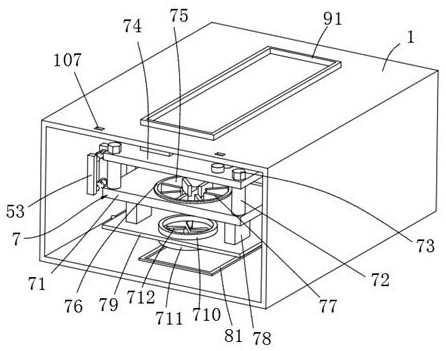
[0080] Example three, please refer to figure 2 and 8 , a converged communication terminal with its own encoding and decoding of optical fiber signals, the structure of this embodiment is roughly the same as that of Embodiment 2, the difference is that:
[0081] The air intake unit 8 includes an air intake frame 81, a dust filter cloth 82, an upper clamping frame 83, a lower clamping frame 84, a water-absorbing pad 85, an inner solid rod 86 and a lower screen plate 87, and the lower middle part of the installation box 1 is inlaid There is an air inlet frame 81, and the outer side of one end of the air inlet frame 81 located in the installation box 1 is fixedly sleeved with an upper clamping frame 83, and the outer side of the end of the air inlet frame 81 located outside the installation box 1 is fixedly sleeved with a lower clamping frame 84 , In the air intake frame 81, dust filter cloth 82, water-absorbing pad one 85 and lower net plate 87 are installed successively from t...
PUM
 Abstract
Description
Claims
Application Information
 - R&D Engineer
- R&D Manager
- IP Professional
- Industry Leading Data Capabilities
- Powerful AI technology
- Patent DNA Extraction
Browse by: Latest US Patents, China's latest patents, Technical Efficacy Thesaurus, Application Domain, Technology Topic, Popular Technical Reports.
© 2024 PatSnap. All rights reserved.Legal|Privacy policy|Modern Slavery Act Transparency Statement|Sitemap|About US| Contact US: help@patsnap.com