Machining residue cleaning and transferring device for laser-induced forming machine tool

A technology of laser induction and transfer device, used in laser welding equipment, metal processing equipment, manufacturing tools, etc., can solve problems such as abnormal operation and use of equipment, distortion of sensitive positions of equipment, hidden dangers of waste transfer safety, etc., to avoid moving speed. Too fast, stable rotation effect, avoid overheating effect

Pending Publication Date: 2022-04-19
胡嘉鑫
View PDF1 Cites 0 Cited by
  • Summary
  • Abstract
  • Description
  • Claims
  • Application Information

AI Technical Summary

Problems solved by technology

[0007] In order to solve the above-mentioned technical problems, the present invention provides a laser-induced forming machine tool processing residual material cleaning and transfer device to solve the problem of high temperature of waste material that cannot be transported to the outer end of the equipment even after the material is cut by laser. It will still cause burning to the equipment, resulting in distortion of the sensitive position of the equipment, affecting the normal operation and use of the equipment, and the residual waste remains in a high temperature state. There are potential safety hazards when the staff transfers the waste.

Method used


Image

  • Machining residue cleaning and transferring device for laser-induced forming machine tool
  • Machining residue cleaning and transferring device for laser-induced forming machine tool
  • Machining residue cleaning and transferring device for laser-induced forming machine tool

Examples


Embodiment

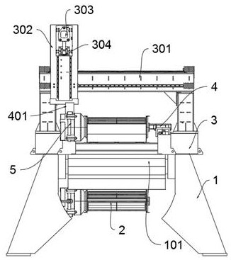
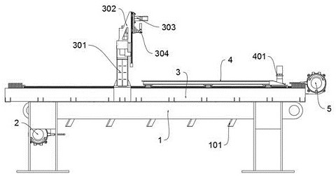
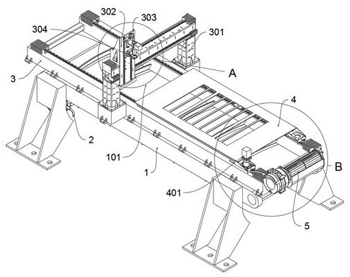
[0044]as attached figure 1 To attach Figure 8 Shown:

[0045] The present invention provides a laser-induced forming machine tool processing residue cleaning and transfer device, including: a frame body 1;

[0046] The four corners of the bottom of the frame body 1 are provided with supporting legs, and the front and rear ends of the frame body 1 are provided with rotating rods; the middle position of the two supporting legs at the rear end of the frame body 1 is fixedly connected with the driving part A2; the frame body 1 includes: a conveyor belt Circle 101, the outer end of the conveyor belt circle 101 is provided with twelve arc panels, the distance between each adjacent two arc panels is the same, and each arc panel is inclined, and the conveyor belt circle 101 passes through the rotation rod at both ends of the frame body 1. Cooperate and rotate to be connected at the upper end position of support body 1.

[0047] Wherein, a motor is arranged on the left side of the ...


PUM


Abstract

The invention provides a residual material cleaning and transferring device for laser-induced forming machine tool machining, relates to the technical field of laser machine tool material machining, and solves the problems that after materials are cut through laser in the prior art, generated waste cannot be transferred to the outer end of equipment even if the waste is transferred to the outer end of the equipment, the high temperature of residual waste can still burn the equipment, and the equipment cannot be damaged. The problems that the sensitive position of equipment is distorted, the equipment cannot operate and use normally, residual waste is continuously in a high-temperature state, and potential safety hazards exist when workers transfer the waste are solved. A machining residue cleaning and transferring device of a laser-induced forming machine tool comprises a frame body. Supporting legs are arranged at the four corners of the bottom of the frame body, and rotating rods are arranged at the front end and the rear end of the frame body. Due to the fact that the sliding rails are arranged at the left end and the right end of the top of the machine tool frame, and the damping elastic pieces are arranged at the front end and the rear end of each sliding rail, the problems that the feeding piece moves too fast in the moving process, and materials above the feeding piece are collided and deformed through inertia can be solved.

Description

technical field [0001] The invention belongs to the technical field of laser machine tool material processing, and more specifically relates to a laser-induced forming machine tool processing residue cleaning and transferring device. Background technique [0002] Laser beam processing is a processing method based on the infrared radiation of the laser system and the inherent heat of the material to heat, melt, ablate or even vaporize the material for drilling, cutting, welding and surface heat treatment. The laser converts electrical energy into light energy , to generate the required laser beam, through the lens to focus the laser into a very small spot and irradiate the surface to be processed, which can melt and vaporize a certain substance in a few thousandths of a second, or even shorter time, to achieve ablation processing The principle is that when the laser with extremely high energy density is irradiated on the surface to be processed, the light energy is absorbed b...

Claims


Application Information

Patent Timeline
Patent Type & Authority Applications(China)
IPC IPC(8): B23K26/142B23K26/16B23K26/38B23K26/70
CPCB23K26/38B23K26/702B23K26/16B23K26/142
Inventor 胡嘉鑫
Owner 胡嘉鑫
Why Eureka
Try Eureka