Automatic fixed-distance flame cutting equipment for curved-surface materials and using method of automatic fixed-distance flame cutting equipment

A flame cutting, automatic technology, applied in the field of mechanical processing, can solve the problem that the flame cutting head cannot be at the same distance from the workpiece, the optimal cutting position of the flame cutting head cannot always be guaranteed, and there is no automatic distance setting function.

Pending Publication Date: 2022-04-19
无锡桥联焊割成套设备有限公司
View PDF7 Cites 0 Cited by
  • Summary
  • Abstract
  • Description
  • Claims
  • Application Information

AI Technical Summary

Problems solved by technology

[0005] The purpose of the present invention is to solve the problem that the flame cutting equipment in the prior art has no automatic distance fixing function, and the flame cutting head and the workpiece cannot always keep the same distance during the cutting process, so when the flame cutting equipment cuts the curved surface workpiece, due to The surface of the curved workpiece is not flat, the distance between the flame cutting head and the workpiece will change during cutting, it is easy to fail to cut or the flame cutting head hits the workpiece, and it is impossible to always ensure that the flame cutting head is in the best cutting position. An automatic fixed-distance flame cutting equipment for curved surface materials and its application method are proposed

Method used


Image

  • Automatic fixed-distance flame cutting equipment for curved-surface materials and using method of automatic fixed-distance flame cutting equipment
  • Automatic fixed-distance flame cutting equipment for curved-surface materials and using method of automatic fixed-distance flame cutting equipment
  • Automatic fixed-distance flame cutting equipment for curved-surface materials and using method of automatic fixed-distance flame cutting equipment

Examples


Embodiment Construction

[0032] The following will clearly and completely describe the technical solutions in the embodiments of the present invention with reference to the accompanying drawings in the embodiments of the present invention. Obviously, the described embodiments are only some, not all, embodiments of the present invention.

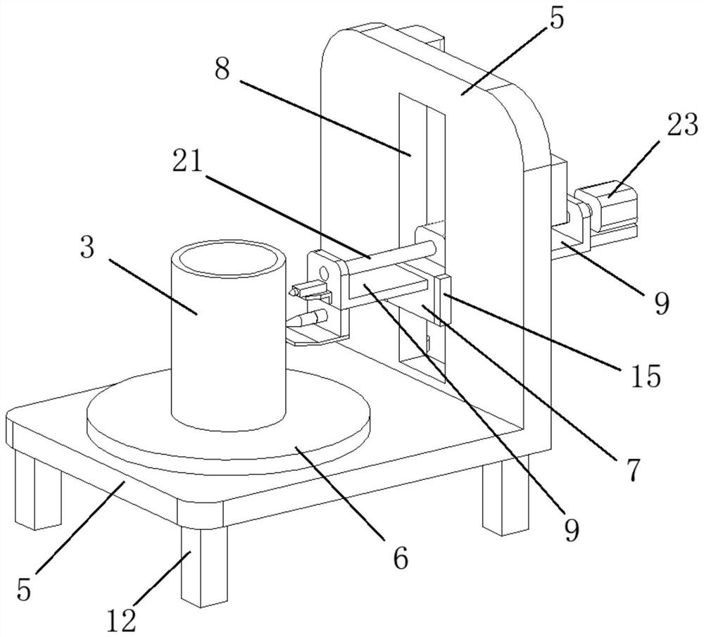
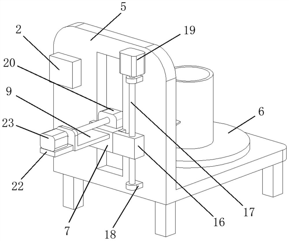
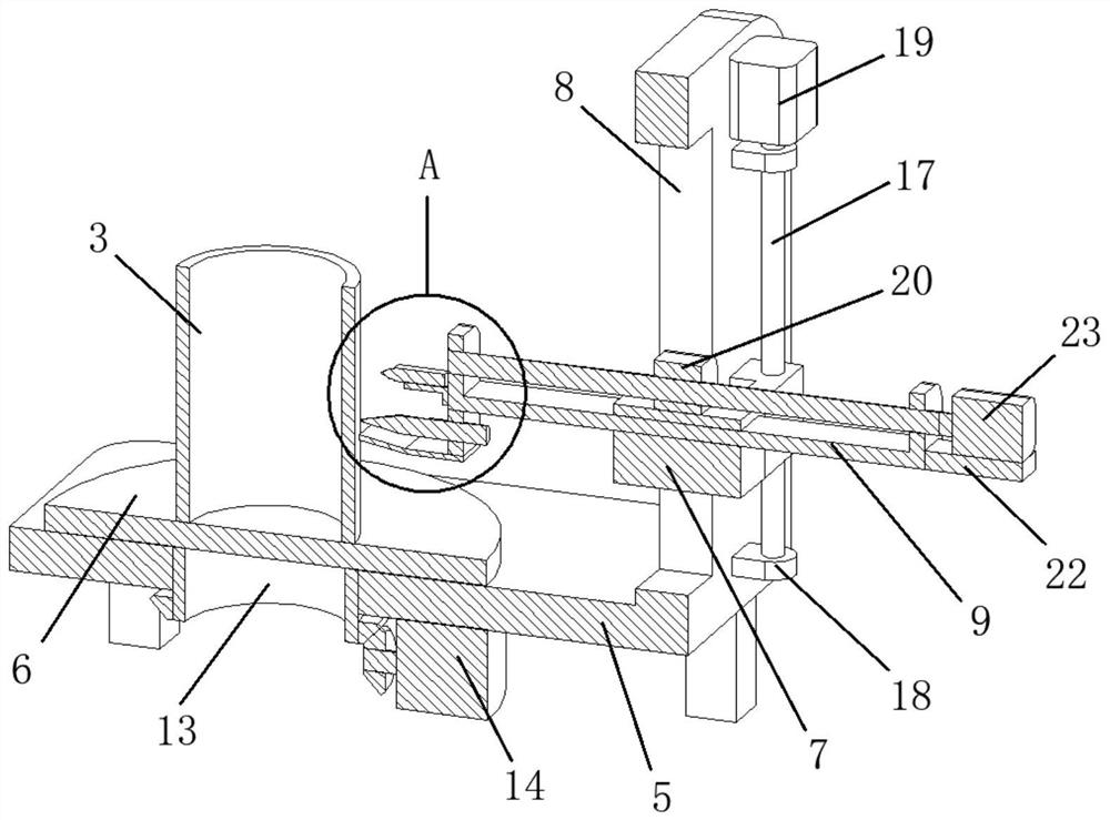
[0033] refer to Figure 1-5 , an automatic fixed-distance flame cutting equipment for curved surface materials, including a flame cutting head 1, a processing controller 2, a workpiece 3, and a distance measuring sensor 4, the processing controller 2 needs to be connected to an external power supply through a wire, and the distance measuring sensor 4 is connected to the processing through a wire The controller 2 is electrically connected, and also includes:

[0034] L-shaped main frame 5, processing controller 2 is fixed on one side of L-shaped main frame 5;

[0035] Rotary disc 6, the rotary disc 6 is arranged on one side of the L-shaped main frame 5, the workpiece...


PUM


Abstract

The invention relates to the technical field of machining, in particular to automatic fixed-distance flame cutting equipment for curved surface materials, which comprises a flame cutting head, a processing controller, a workpiece and a distance measuring sensor, and further comprises an L-shaped main body frame, and the processing controller is fixed on one side of the L-shaped main body frame; the rotating disc is arranged on one side of the L-shaped main body frame, a workpiece is arranged on the upper side of the rotating disc, and a rotating driving assembly is arranged between the rotating disc and the L-shaped main body frame; a sliding hole is formed in one side of the L-shaped main body frame, the sliding block can slide on the inner side of the sliding hole, and a lifting adjusting assembly is arranged between the sliding block and the L-shaped main body frame. By arranging the flame cutting head, the processing controller, the workpiece, the distance measuring sensor, the L-shaped main body frame, the rotating disc, the sliding block, the sliding hole and the U-shaped telescopic frame, the automatic cutting device has the functions of automatic cutting, automatic distance fixing, automatic lifting adjustment and the like.

Description

technical field [0001] The invention relates to the technical field of mechanical processing, in particular to an automatic fixed-distance flame cutting device for curved surface materials and a use method thereof. Background technique [0002] Machining refers to the process of changing the shape or performance of a workpiece through a mechanical device. According to the difference in processing method, it can be divided into cutting processing and pressure processing. [0003] Flame cutting is a common method for rough machining of steel plates. Flame cutting is gas cutting. Traditionally, acetylene gas is used for cutting, and later propane is used for cutting. Now natural gas cutting has appeared, and because of its abundant reserves, cheap price, and no pollution, it has become the first choice for flame cutting. Natural gas flame cutting generally adds natural gas additives to generate a new type of flame cutting gas. Using this gas for flame cutting can make the cut...

Claims


Application Information

Patent Timeline
IPC IPC(8): B23K7/00B23K7/10
CPCB23K7/005B23K7/006B23K7/102
Inventor 汤文君刘鸿羽毛仁逸
Owner 无锡桥联焊割成套设备有限公司
Why Eureka
Try Eureka