Automatic cooling ring main unit

A technology for automatic cooling and ring network cabinets, applied in the field of ring network cabinets, can solve problems such as poor results, and achieve the effect of providing convenience, good heat dissipation, and preventing electrical appliances from burning out.

Pending Publication Date: 2022-04-15
江西士达能源科技有限公司
View PDF1 Cites 0 Cited by
  • Summary
  • Abstract
  • Description
  • Claims
  • Application Information

AI Technical Summary

Problems solved by technology

[0005] In order to overcome the shortcomings of the existing ring network cabinets that only rely on exhaust air to cool down, the technical problem to be solved is to provide an automatic cooling ring network cabinet that can achieve a better heat dissipation effect by blowing out cold air with moisture

Method used


Image

  • Automatic cooling ring main unit
  • Automatic cooling ring main unit
  • Automatic cooling ring main unit

Examples


Embodiment 1

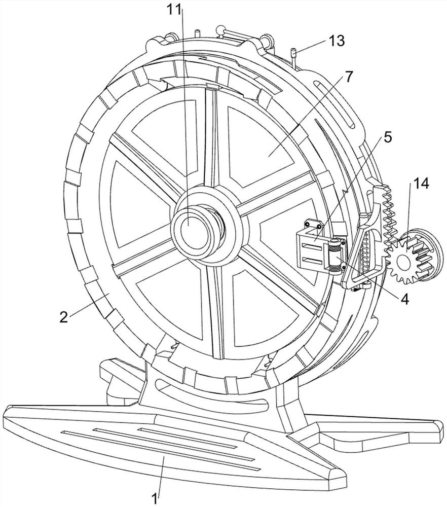
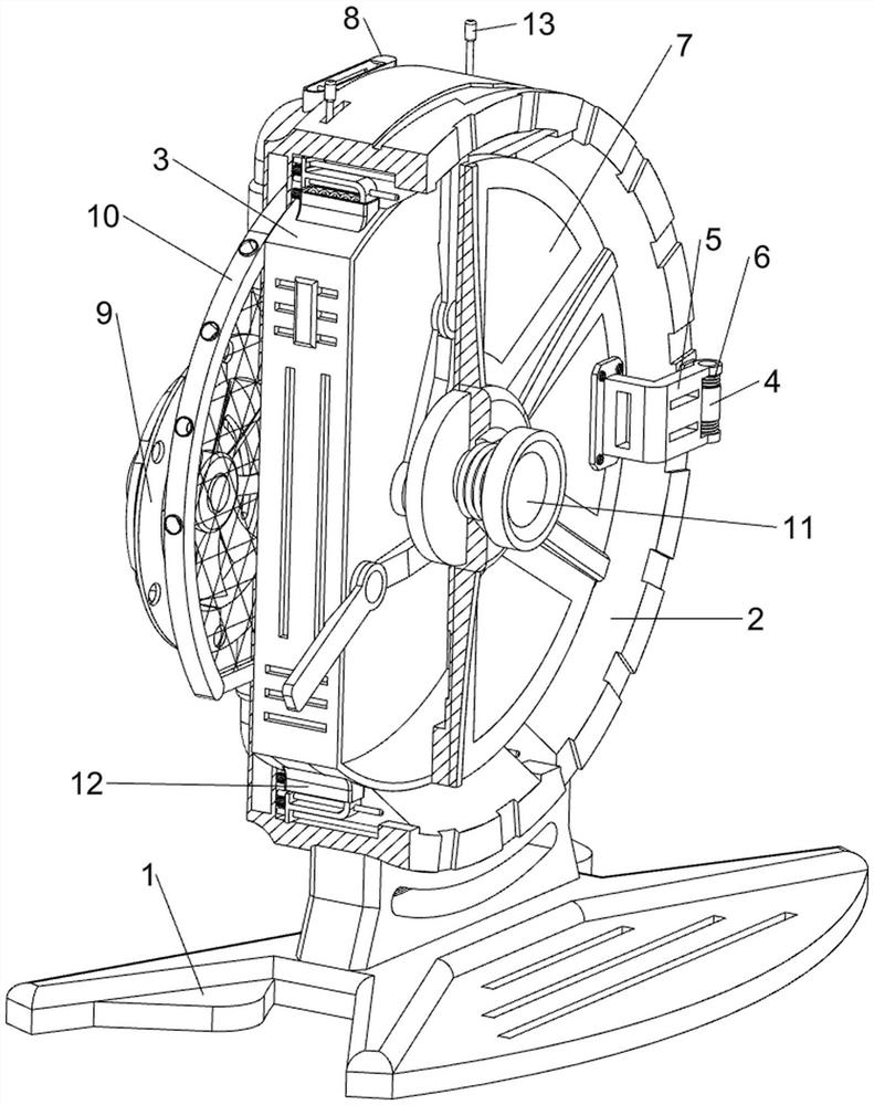
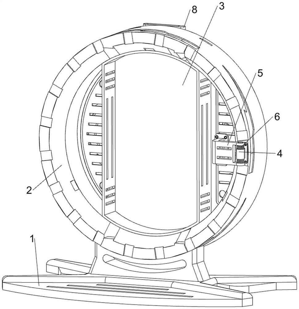
[0039] An automatic cooling ring network cabinet, in Figure 1-3 As shown in , it includes a support frame 1, a protective box 2, an installation cabinet 3, a first connecting block 4, a second connecting block 5, a torsion spring 6, a protective plate 7, a water adding bucket 8, a cooling mechanism 9, and a liquid cooling mechanism 10 And the clamping mechanism 11, the top of the support frame 1 is connected with the protective box 2 by screw connection, the protective box 2 is circular, and the right side of the front wall of the protective box 2 is connected with the first connecting block 4 by screw connection, the first The connecting block 4 is rotatably provided with a second connecting block 5, and a torsion spring 6 is connected between the upper and lower sides of the second connecting block 5 and the first connecting block 4, and the rear side of the left part of the second connecting block 5 is welded for protection. The protective plate 7, the protective plate 7 c...

Embodiment 2

[0045] On the basis of Example 1, in figure 2 , Figure 10 and Figure 11 As shown in , it also includes an ejection mechanism 12 that can automatically eject the installation cabinet 3 to the front side. The ejection mechanism 12 includes a third connecting block 120, a limit rod 121, a slider 122, a compression spring 123, and a tension spring 124. and guide rod 125, the upper and lower side walls of the installation cabinet 3 are symmetrically connected with the third connecting block 120 by means of bolt connection, and the four third connecting blocks 120 are slidingly provided with the installation cabinet 3 to slide forward more. The long-distance slide block 122, the four slide blocks 122 and the third connecting block 120 on the same side are all connected with tension springs 124, and the upper and lower sides of the inner rear side of the protective box 2 are symmetrically provided with guiding guides for guiding. Rod 125, four slide blocks 122 are all slidably c...


PUM


Abstract

The invention relates to a ring main unit, in particular to an automatic cooling ring main unit. The automatic cooling ring main unit provided by the invention can achieve a better heat dissipation effect by blowing out cold air with moisture. An automatic cooling ring main unit comprises a supporting frame, a protection box, a first connecting block, a second connecting block, a torsion spring and the like, the protection box is arranged at the top of the supporting frame and is round, the first connecting block is arranged on the right side of the front wall of the protection box, and the second connecting block is rotationally arranged on the first connecting block. Torsion springs are connected between the upper side and the lower side of the second connecting block and the first connecting block. The high-voltage electric appliance is installed in the installation cabinet, when the temperature sensor senses that the temperature in the installation cabinet is larger than the preset value, the driving motor is controlled to work, the fan blades rotate to blow out air to achieve the cooling effect, automatic induction cooling is achieved, waste is avoided, automation is achieved, and the electric appliance can be prevented from being burnt out.

Description

technical field [0001] The invention relates to a ring network cabinet, in particular to an automatic cooling ring network cabinet. Background technique [0002] The ring network cabinet is a group of transmission and distribution electrical equipment installed in a metal or non-metal insulated cabinet or made into an assembled interval ring network power supply unit. The high-voltage electrical appliances installed in the ring network cabinet will generate a lot of heat when they work. If it is not dispersed in time, it will limit the service life of the electrical components in the cabinet and increase the cost of use. [0003] The publication number is CN207967730U, a waterproof and cooling ring network cabinet. The ring network cabinet is composed of an internal frame, a buried foundation, a control cabinet, a negative pressure fan, and a low-voltage power supply. The design of the buried foundation is adopted to separate the inner cabinet and the control cabinet, which...

Claims


Application Information

Patent Timeline
Patent Type & Authority Applications(China)
IPC IPC(8): H02B13/035H02B13/045H02B1/56
Inventor 陈林荣何根彭春鸣刘辉
Owner 江西士达能源科技有限公司
Why Eureka
Try Eureka