
Backlight module and display device

A technology of backlight module and display device, which is applied in the directions of identification device, optics, nonlinear optics, etc. It can solve the problems of deformation and collapse, affect the optical effect, increase the overall thickness of the backlight module and production cost, etc., and achieve the effect of good optical performance

Pending Publication Date: 2022-04-15
CORETRONIC OPTOTECHSUZHOU CO LTD
View PDF7 Cites 0 Cited by
  • Summary
  • Abstract
  • Description
  • Claims
  • Application Information

AI Technical Summary

Problems solved by technology

However, in this method, a supporting structure must be added under the optical diaphragm group to support the optical diaphragm group, so as to avoid the deformation and collapse of the optical diaphragm group under the environment of high and low temperature changes due to cold shrinkage and thermal expansion, thereby affecting optical effect
[0003] However, increasing the supporting structure will increase the overall thickness of the backlight module and the production cost

Method used


Image

  • Backlight module and display device
  • Backlight module and display device
  • Backlight module and display device

Examples


Embodiment Construction

[0047] The foregoing and other technical contents, features and effects of the present invention will be clearly presented in the following detailed description of a preferred embodiment with reference to the accompanying drawings. The directional terms mentioned in the following embodiments, such as: up, down, left, right, front or back, etc., are only referring to the directions of the drawings. Accordingly, the directional terms are used to illustrate and not to limit the invention.

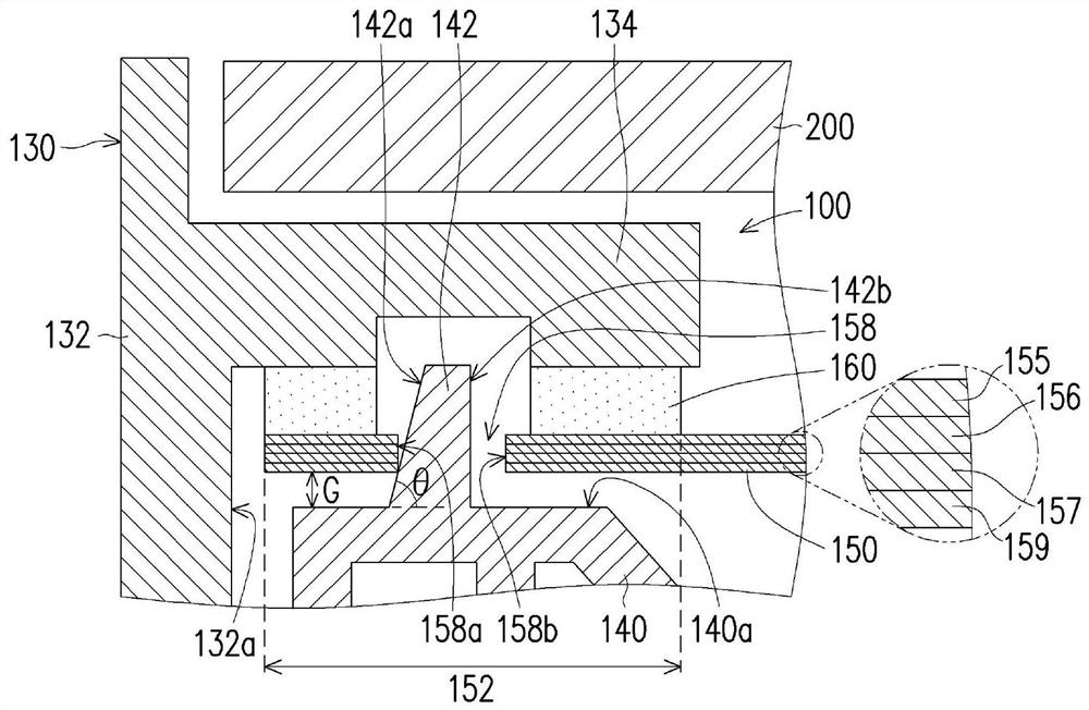
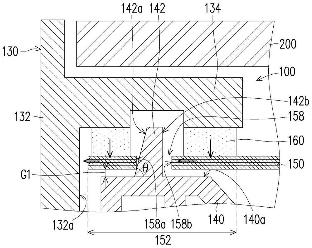
[0048] figure 1 is a schematic side view of a display device according to an embodiment of the present invention. In particular, for the sake of clarity, figure 1 Only the parts near the two sides of the display device are shown. Please refer to figure 1 , the display device 10 of this embodiment includes a backlight module 100 and a display panel 200, wherein the backlight module 100 is, for example, a direct type backlight (direct type backlight) module, and in other embodiments, the bac...


PUM


Abstract

A backlight module comprises a back plate, a light-emitting assembly, a front frame, a rubber frame, an optical film set and an elastic piece. The light-emitting assembly is arranged on the back plate. The front frame is provided with an annular outer wall surrounding the back plate and a covering part protruding out of the inner surface of the annular outer wall. The cover portion extends from an inner surface of the annular outer wall to a position above a periphery of the back plate. The rubber frame is arranged between the periphery and the front frame and provided with an upper surface far away from the back plate and protruding columns protruding out of the upper surface, and each protruding column is provided with an inclined face inclining towards the annular outer wall. The optical film set is arranged on the side, away from the back plate, of the light-emitting assembly and provided with a surrounding area corresponding to the rubber frame. The surrounding area is located between the covering part and the rubber frame and provided with an opening. A gap is formed between the peripheral area and the upper surface. The protruding columns penetrate through the opening, and the inclined face of each protruding column makes contact with the wall face beside the opening. The elastic member is disposed between the peripheral area and the front frame. The invention also provides a display device comprising the backlight module. The backlight module and the display device can reduce the probability of deformation and collapse of the optical film group.

Description

technical field [0001] The present invention relates to an optical module and a display device, and in particular to a backlight module and a display device. Background technique [0002] The display device includes a backlight module and a display panel. The backlight module can provide a surface light source to the display panel so that users can watch images displayed on the display panel. In current display devices, a common practice is to use a plastic frame to carry the optical film group, and fix the optical film group to the protrusion structure of the plastic frame. However, in this method, a supporting structure must be added under the optical diaphragm group to support the optical diaphragm group, so as to avoid the deformation and collapse of the optical diaphragm group under the environment of high and low temperature changes due to cold shrinkage and thermal expansion, thereby affecting optical effect. [0003] However, increasing the supporting structure wi...

Claims


Application Information

Patent Timeline
Patent Type & Authority Applications(China)
IPC IPC(8): G09F9/30G02F1/13357
Inventor 徐麟颉
Owner CORETRONIC OPTOTECHSUZHOU CO LTD
Learn More