
Three-dimensional light path experiment demonstration method

A demonstration method and three-dimensional technology, which is applied in the field of physical experiment demonstration, can solve the problems of small observation range and lack of spatial three-dimensional sense of light, and achieve the effect of expanding the scope.

Pending Publication Date: 2022-04-15
TONGAN NO 1 MIDDLE SCHOOL FUJIAN PROV
View PDF0 Cites 1 Cited by
  • Summary
  • Abstract
  • Description
  • Claims
  • Application Information

AI Technical Summary

Problems solved by technology

[0006] The following problems exist in the existing experimental device for the convergence of convex lenses: (1) The "convergence of several special light rays" uses a linear light source, the light phenomenon lacks a three-dimensional sense of space, and the observation range is small

Method used


Image

  • Three-dimensional light path experiment demonstration method
  • Three-dimensional light path experiment demonstration method
  • Three-dimensional light path experiment demonstration method

Examples


Embodiment Construction

[0030] In the following detailed description, reference is made to the accompanying drawings, which form a part hereof, and which show by way of illustration specific embodiments in which the invention may be practiced. In this regard, directional terms such as "top", "bottom", "left", "right", "upper", "lower", etc. are used with reference to the orientation of the figures being described. Because components of an embodiment may be positioned in several different orientations, directional terminology is used for purposes of illustration and is by no means limiting. It is to be understood that other embodiments may be utilized or logic changes may be made without departing from the scope of the present invention. The following detailed description should therefore not be taken in a limiting sense, and the scope of the invention is defined by the appended claims.

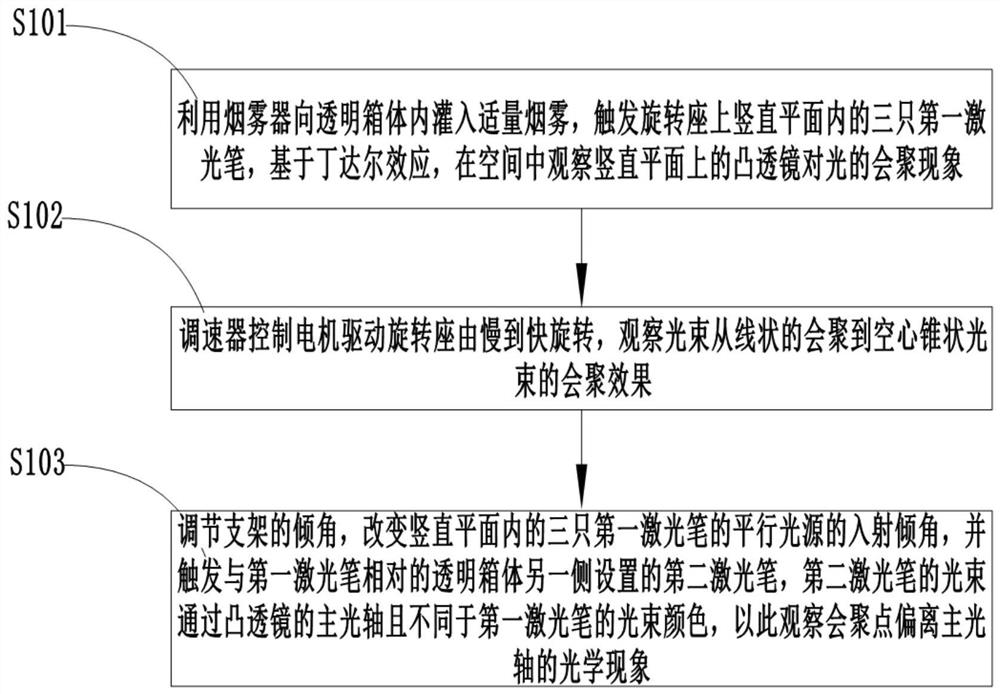
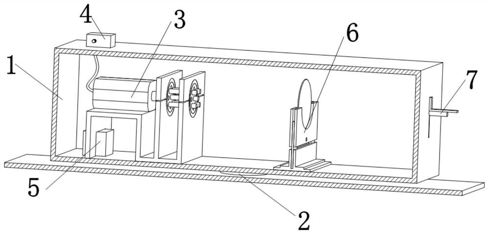
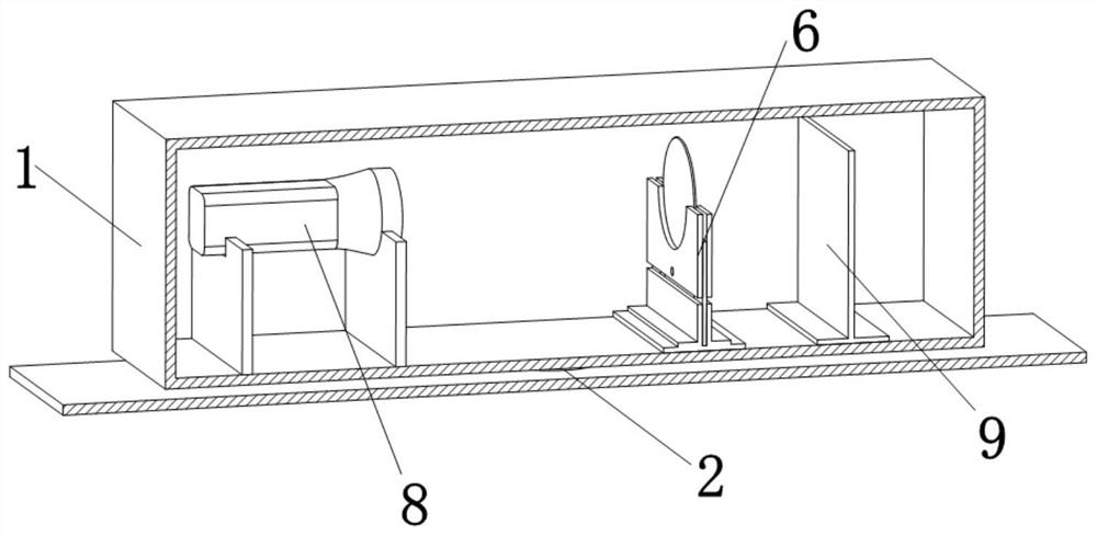
[0031] figure 1 Shows a flow chart of a stereoscopic optical path experiment demonstration method according to a...


PUM


Abstract

The invention discloses a three-dimensional light path experiment demonstration method, which comprises the following steps of: injecting a proper amount of smoke into a transparent box body by using a smoke device, triggering three first laser pens in a vertical plane on a rotating seat, and observing a light convergence phenomenon of a convex lens on the vertical plane in a space based on a Tyndall effect; the speed regulator controls the motor to drive the rotating seat to rotate from slow to fast, and the convergence effect of the light beams from linear convergence to hollow conical light beams is observed; the inclination angle of the support is adjusted, the incidence inclination angle of parallel light sources of the three first laser pens in the vertical plane is changed, a second laser pen arranged on the other side, opposite to the first laser pens, of the transparent box is triggered, and light beams of the second laser pen pass through the main optical axis of the convex lens and are different from the light beams of the first laser pens in color. Therefore, the optical phenomenon that the convergence point deviates from the principal optical axis is observed. According to the invention, the experiment is expanded from plane two-dimensional observation to three-dimensional space and progressive layer by layer, the exploration method is changed from particularity to universality, and the demonstration process is more scientific and complete.

Description

technical field [0001] The invention relates to a physical experiment demonstration method, and in particular to a stereoscopic optical path experiment demonstration method. Background technique [0002] Eighth grade students learn "Scientific Inquiry: Convex Lens Imaging" based on "Refraction of Light". The first class requires students to understand the basic knowledge of lenses, which is the basis for learning the law of lens imaging and the application of lenses in daily life. However, it is difficult for students to understand the core concepts of optical center, focus, and focal length, as well as the effect of lenses on light. Since we have not experienced the knowledge construction link based on effective experiments, our learning can only stay at the shallow level of learning mechanical memory. Although the teachers try to construct the core concepts about lenses through demonstration experiments in class, the existing domestic experimental research on the converg...

Claims


Application Information

Patent Timeline
IPC IPC(8): G09B23/22
CPCG09B23/22
Inventor 蔡元桢
Owner TONGAN NO 1 MIDDLE SCHOOL FUJIAN PROV
Learn More