Vehicle lamp module system with extremely narrow opening and capable of being freely combined
A free and car lighting technology, applied in the direction of headlights, vehicle parts, lighting device parts, etc., can solve the problem that it is difficult to meet the trend of free combination modeling, cannot be redistributed to a specified angle, and light can only travel in a straight line. , to achieve the effect of flexible light distribution angle, good light effect and uniformity, and easy control
- Summary
- Abstract
- Description
- Claims
- Application Information
AI Technical Summary
Problems solved by technology
Method used
Image
Examples
Embodiment 1
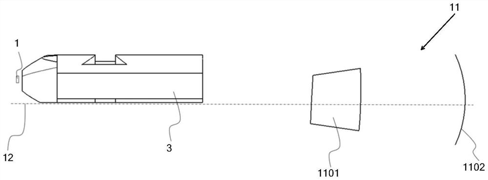
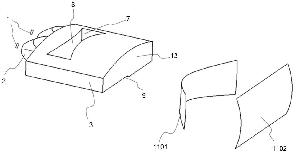
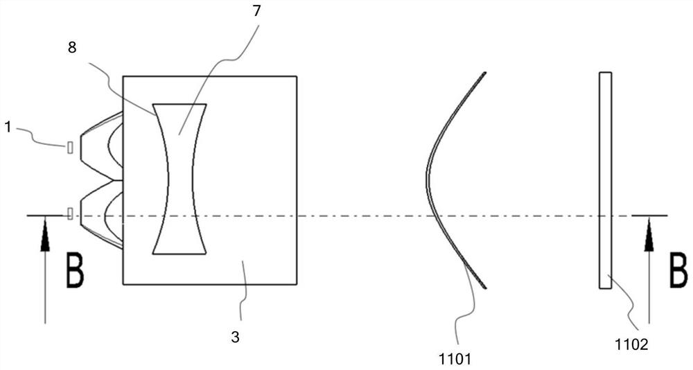
[0075] Such as Figure 1-7 As shown, this embodiment provides a vehicle light module system with extremely narrow openings that can be freely assembled, which is characterized in that it includes a light source assembly, a collimator assembly, a primary light distribution mirror assembly, and a projection lens 11 . The collimator assembly is arranged on the primary light distribution lens assembly, the light source assembly is arranged on the side of the collimator assembly away from the primary light distribution lens assembly, and the projection lens 11 is arranged on the side of the primary light distribution lens assembly away from the collimator assembly, The light emitted by the light source assembly is incident into the primary light distribution mirror assembly through the collimator assembly, and the light emitted from the primary light distribution mirror assembly is emitted through the projection lens 11. The primary light distribution mirror assembly is provided wit...
Embodiment 2
[0080] Such as Figure 8-14 As shown, the difference between this embodiment and Embodiment 1 is that the light source component is a high beam light source 4 , the collimator component is a high beam collimator 5 , and the primary light distribution lens component is a high beam primary light distribution lens 6 .
[0081] A second cut-off line structure 10 is arranged on the high-beam primary light distribution mirror 6 , and the second cut-off line structure 10 is arranged on the upper surface of the high-beam primary light distribution mirror 6 .
[0082] In other embodiments, the second cut-off line structure 10 may not be set on the high-beam primary light distribution mirror 6, such as Figure 15 and Figure 16 shown.
Embodiment 3
[0084] Such as Figures 17-27 As shown, the difference between this embodiment and Embodiment 1 is that the light source assembly includes a low-beam light source 1 and a high-beam light source 4, and the primary optics collimator assembly includes a low-beam collimator 2 and a high-beam collimator 5. The primary light distribution lens assembly includes the low beam primary light distribution lens 3 and the high beam primary light distribution lens 6 .
[0085] The low-beam collimator 2 is set on the low-beam primary light distribution mirror 3, the high-beam collimator 5 is set on the high-beam primary light distribution mirror 6, and the light emitted by the low-beam light source 1 enters the low-beam through the low-beam collimator 2 In the primary light distribution mirror 3, the light emitted by the high-beam light source 4 passes through the high-beam collimator 5 and enters the high-beam primary light distribution mirror 6, and the light emitted by the low-beam primary...
PUM
 Abstract
Description
Claims
Application Information
 - R&D Engineer
- R&D Manager
- IP Professional
- Industry Leading Data Capabilities
- Powerful AI technology
- Patent DNA Extraction
Browse by: Latest US Patents, China's latest patents, Technical Efficacy Thesaurus, Application Domain, Technology Topic, Popular Technical Reports.
© 2024 PatSnap. All rights reserved.Legal|Privacy policy|Modern Slavery Act Transparency Statement|Sitemap|About US| Contact US: help@patsnap.com


