Small-radius vertical shaft erecting device and using method

A technology with small radius and vertical shaft, applied in the direction of ladders, buildings, building structures, etc., can solve the problems of poor high-altitude operation, inconvenient operation of erection, inconvenient movements, etc., to achieve increased efficiency, easy control and adjustment, The effect of increasing friction

Pending Publication Date: 2021-06-29
GUIZHOU ELECTRIC POWER DESIGN INST
View PDF0 Cites 0 Cited by
  • Summary
  • Abstract
  • Description
  • Claims
  • Application Information

AI Technical Summary

Problems solved by technology

[0002] In tunnels, electrical equipment, and construction industries, small-radius shafts will be excavated or concreted to facilitate the installation of necessary equipment. It is very inconvenient to operate inside the small-radius shaft, and workers need to climb up and down.
[0003] Staircase-like climbing facilities are installed on the outside of the existing shaft, and lifting equipment is used inside, and the safety belts worn by workers are used for high-altitude hoisting operations. When workers are in the suspended state, various actions are inconvenient, which affects the construction of small-radius shafts. The efficiency of the rack, and the safety of working at heights is still relatively poor

Method used


Image

  • Small-radius vertical shaft erecting device and using method
  • Small-radius vertical shaft erecting device and using method
  • Small-radius vertical shaft erecting device and using method

Examples


Embodiment Construction

[0038] The following will clearly and completely describe the technical solutions in the embodiments of the present invention with reference to the accompanying drawings in the embodiments of the present invention. Obviously, the described embodiments are only some, not all, embodiments of the present invention. Based on the embodiments of the present invention, all other embodiments obtained by persons of ordinary skill in the art without making creative efforts belong to the protection scope of the present invention.

[0039] In the description of the present invention, it should be noted that the terms "center", "upper", "lower", "left", "right", "vertical", "horizontal", "inner", "outer" etc. The indicated orientation or positional relationship is based on the orientation or positional relationship shown in the drawings, and is only for the convenience of describing the present invention and simplifying the description, rather than indicating or implying that the referred d...


PUM


Abstract

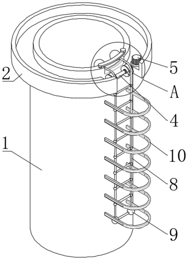
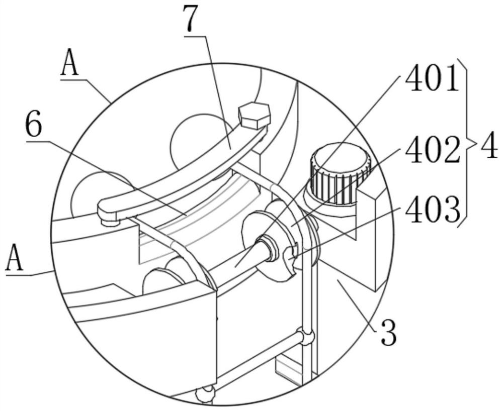
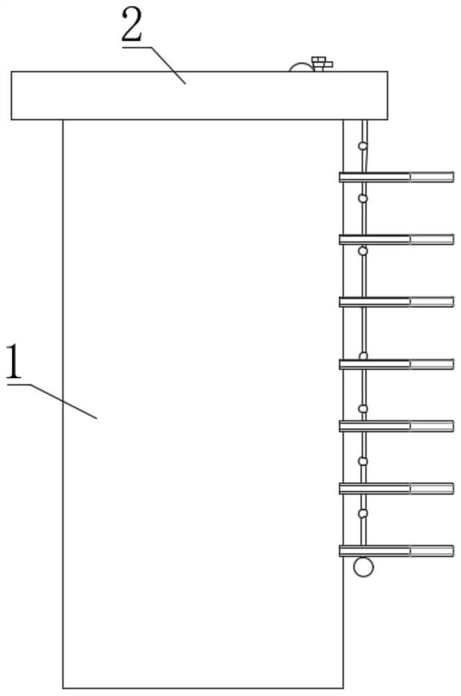
The invention discloses a small-radius vertical shaft erecting device. The small-radius vertical shaft erecting device comprises a vertical shaft body, an outer edge table is fixedly connected to the top of the vertical shaft body, a mounting notch is formed in one side of the outer edge table, a roller structure is arranged in the mounting notch, a gear motor is fixedly connected to the top of the outer edge table, and the output end of the gear motor is in transmission connection with the roller structure. The small-radius vertical shaft erecting device further comprises a rope ladder, the rope ladder is arranged on the outer side of the roller structure, loading balls are arranged at the two ends of the rope ladder, a notch is formed in the top of the vertical shaft body, and the rope ladder is located on the inner side of the notch. The problems that in the prior art, the internal erecting efficiency of a small-radius vertical shaft is low, and the high-altitude operation safety is poor are solved.

Description

technical field [0001] The invention relates to a small-radius shaft erecting device and a using method, belonging to the technical field of erecting in construction. Background technique [0002] In tunnels, electrical equipment, and construction industries, small-radius shafts will be excavated or concreted to facilitate the installation of necessary equipment. It is very inconvenient to set up a frame inside the small-radius shaft, and workers need to climb up and down. [0003] Staircase-like climbing facilities are installed on the outside of the existing shaft, and lifting equipment is used inside, and workers wear safety belts for high-altitude hoisting operations. When workers are in the suspended state, various actions are inconvenient, which affects the internal construction of small-radius shafts. The efficiency of the frame, and the safety of working at heights is relatively poor. Contents of the invention [0004] The purpose of the present invention is to so...

Claims


Application Information

Patent Timeline
IPC IPC(8): E06C9/14E06C7/18E06C7/48
CPCE06C9/14E06C7/183E06C7/185E06C7/48
Inventor 纪元勋吴建国李亚鹏常世洪朱律键蒋鸣明杨路
Owner GUIZHOU ELECTRIC POWER DESIGN INST
Why Eureka
Try Eureka