
Data transmission device and display system

A technology for data transmission and equipment, applied in the field of display systems and data transmission equipment, can solve problems such as weak versatility, single product function, single product, etc., to reduce the complexity of management and use, convenient and fast operation, and simplified operation The effect of the process

Pending Publication Date: 2022-04-12
XIAN NOVASTAR TECH
View PDF5 Cites 0 Cited by
  • Summary
  • Abstract
  • Description
  • Claims
  • Application Information

AI Technical Summary

Problems solved by technology

[0003] At present, the above-mentioned products are all single individuals, the product functions are relatively single, and the versatility is not strong
In order to meet the needs of multiple sites at one time, the user has to purchase a large number of equipment, which makes the site accessories and equipment complex, management and use are complicated, and installation and purchase costs increase

Method used


Image

  • Data transmission device and display system
  • Data transmission device and display system
  • Data transmission device and display system

Examples


no. 1 example

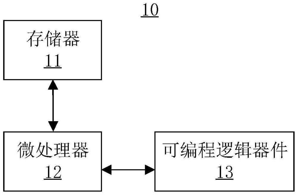
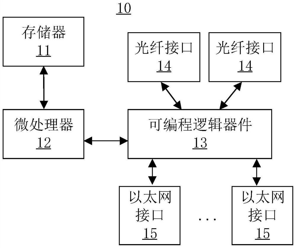
[0039] see figure 1 , a data transmission device 10 disclosed in the first embodiment of the present invention. Such as figure 1 As shown, the data transmission device 10 includes, for example: a memory 11 , a microprocessor 12 and a programmable logic device 13 .

[0040] Specifically, the memory 11 stores, for example, a plurality of mode data in one-to-one correspondence with a plurality of operating modes. The microprocessor 12 is electrically connected to the memory 11, and is configured to receive user input information, and read target mode data corresponding to a target working mode from the plurality of mode data stored in the memory 11 according to the user input information. The programmable logic device 13 is electrically connected to the microprocessor 12 for receiving the target mode data, and operating the target operating mode based on the target mode data.

[0041] Wherein, the memory 11 includes, for example, non-volatile memories such as Flash and EMMC (E...

no. 2 example

[0068] Such as Figure 7 As shown, the second embodiment of the present invention discloses a schematic structural diagram of a display system. The display system 20 includes, for example: a system controller 21 , a data transmission device 22 and a target display screen 23 .

[0069] Specifically, the data transmission device 22 is electrically connected to the system controller 21 . The target display screen 23 is electrically connected to the data transmission device 22 . Wherein, the data transmission device 22 is, for example, the data transmission device disclosed in the aforementioned first embodiment. For the introduction of the data transmission device 22, reference may be made to the first embodiment. For the sake of brevity, the introduction of the data transmission device 22 will not be repeated here.

[0070] Wherein, the mentioned system controller 21 is, for example, the sending card in the LED display control system. Specifically, such as Figure 8 As shown...


PUM


Abstract

Disclosed in an embodiment of the present invention are a data transmission device and a display system, the data transmission device, for example, comprising: a memory in which a plurality of mode data corresponding to a plurality of working modes one by one are stored; the microprocessor is electrically connected with the memory and is used for receiving user input information and reading target mode data corresponding to a target working mode from the multiple pieces of mode data stored in the memory according to the user input information; and the programmable logic device is electrically connected with the microprocessor and is used for receiving the target mode data and running the target working mode based on the target mode data. According to the data transmission equipment disclosed by the embodiment of the invention, the requirements of various application scenes can be met by one piece of equipment.

Description

technical field [0001] The present invention relates to the field of display technology, in particular to a data transmission device and a display system. Background technique [0002] With the rapid development of LED display technology, LED display technology is becoming more and more common, ranging from small street billboards to various performance industries. With the development and popularization of LED display high-resolution trends, it also poses a challenge to the LED industry. In order to meet the higher requirements, stability and ease of use are becoming more and more important. At the same time, in order to solve the problems in the application of LED display technology, some accessory products used to solve high-resolution display have also been born, such as photoelectric converters, distribution lines Devices, etc., to solve some problems that arise on site. [0003] These above-mentioned products are all single individuals at present, and product function...

Claims


Application Information

Patent Timeline
Patent Type & Authority Applications(China)
IPC IPC(8): H04L12/02H04B10/25
Inventor 王松韦桂锋
Owner XIAN NOVASTAR TECH
Learn More