Stator and rotor horizontal assembling device and assembling method of turbine power generation equipment

A turbine power generation and rotor technology, applied in the manufacture of stator/rotor body, etc., can solve the problems of unsuitable turbine power generation devices, and achieve the effects of easy assembly accuracy, high precision, and low noise

Active Publication Date: 2022-04-12
航天科工哈尔滨风华有限公司
View PDF6 Cites 1 Cited by
  • Summary
  • Abstract
  • Description
  • Claims
  • Application Information

AI Technical Summary

Problems solved by technology

[0006]The above two common assembly methods have their own advantages and disadvantages, but they are all aimed at the stator-rotor assembly device of the motor, and are not suitable for turbine power generation devices, turbine power generation devices Different from the structure of the general permanent magnet synchronous motor, the product itself has a turbine drive end component. The drive end of the rotor shaft and the drive components such as the turbine are installed in the turbine housing before assembly to form a semi-finished component of the rotor and turbine.

Method used


Image

  • Stator and rotor horizontal assembling device and assembling method of turbine power generation equipment
  • Stator and rotor horizontal assembling device and assembling method of turbine power generation equipment
  • Stator and rotor horizontal assembling device and assembling method of turbine power generation equipment

Examples


Embodiment 1

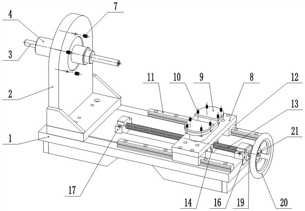
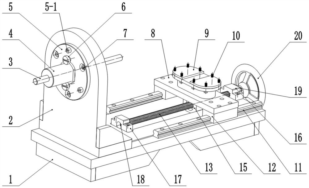
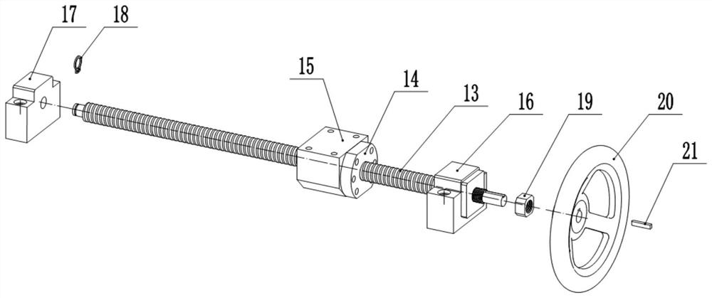
[0045] Embodiment 1: A horizontal stator and rotor assembly device for turbine power generation equipment in this embodiment includes a platform base 1, a casing bent plate bracket 2, a guide shaft rod 3, a positioning guide sleeve 4, a shaft sleeve fixed Center end cover 5, end cover fixing screw 5-1, limit shoulder screw 6, casing fixing screw 7, turbine housing sliding bracket 8, turbine housing adjusting backing plate 9, turbine housing fixing screw 10, a Secondary linear guide rail 11, one pair of sliders 12, ball screw 13, screw nut 14, screw nut seat 15, fixed end seat 16, support end seat 17, retaining ring 18, nut 19, hand wheel 20 and flat key twenty one;

[0046] The casing bent plate bracket 2 is used to install the stator and the casing assembly, the casing bent plate bracket 2 is fixed on the left end of the platform base 1, and a pair of linear guide rails 11 are installed on the axis parallel to the stator and rotor of the turbine power generation equipment On...

Embodiment 2

[0048] Embodiment 2: A method for assembling the stator and rotor of a turbine power generation equipment in this embodiment includes:

[0049] Before assembling, place the sliding bracket 8 of the turbine casing on the rightmost end of the linear guide rail 11, and use the connection hole at the outer end of the turbine generator casing to align the outer circle of the front end of the centering shaft with the positioning guide sleeve 4 to correspond to the turbine generator casing. The inner hole cooperates with the centering; the center is limited, and the stator and the casing assembly are fixed on the casing bending plate bracket 2 with the casing fixing screw 7, and the positioning guide bushing 4 is rotated so that the shoulder of the bushing is stuck in the limit position In the limit shoulder of the shoulder screw 6, it is ensured that when the guide shaft rod 3 moves axially left and right in the center hole of the positioning guide sleeve 4, the positioning guide sle...


PUM


Abstract

The invention discloses a horizontal stator and rotor assembling device and method for turbine power generation equipment, and belongs to the technical field of turbine power generation equipment assembling. The problem that the assembling technology in the prior art is not suitable for coaxial assembling of the stator and the rotor of the turbine power generation equipment is solved. According to the technical scheme, a casing bent plate support is used for installing a stator and casing combination and fixed to the left end of a platform base, a linear guide rail is installed on the right side of the platform base, and a sliding block is assembled on the linear guide rail; the turbine shell sliding bracket is used for installing a rotor and turbine semi-finished product assembly and fixed to the sliding block, the lead screw nut is fixedly installed on the sliding bracket through the lead screw nut base, the ball screw and the lead screw nut are installed in a threaded fit mode, and the hand wheel is used for rotating the ball screw to drive the sliding bracket to move horizontally along the linear guide rail. According to the tool, it is ensured that stator and rotor assemblies of the turbine power generation device are accurate in positioning, reliable in clamping and convenient to assemble, it is effectively ensured that the stator and the rotor do not make adsorption contact or collide in the assembling process, and the assembling quality and efficiency are effectively improved.

Description

technical field [0001] The invention relates to a stator-rotor assembly device and assembly method, in particular to a stator-rotor horizontal assembly device and assembly method for turbine power generation equipment, belonging to the technical field of turbine power generation equipment assembly. Background technique [0002] The structure of the turbo generator has the same coaxial installation of the stator and rotor as the permanent magnet motor. For small and medium-sized turbo generators, due to the magnetic effect of the permanent magnet of the generator rotor, there is a large gap between the generator rotor and the stator during the overall assembly. Due to the strong magnetic adsorption force, the stator and rotor are easily adsorbed together during the assembly process, resulting in quality problems such as winding insulation and bearing scratches. Once adsorbed together, it is difficult to separate, which will affect the assembly work. If it is forced to separat...

Claims


Application Information

Patent Timeline
Patent Type & Authority Applications(China)
IPC IPC(8): H02K15/02
Inventor 王相理关超许占宇周凯衣伟关博文陈鹏强戴占洋张晶刘明
Owner 航天科工哈尔滨风华有限公司
Why Eureka
Try Eureka