Nuclear power equipment pipeline inspection device

An inspection device and pipeline technology, which is applied in the inspection field, can solve problems such as inconvenient operation, narrow pipeline space, and low inspection efficiency, and achieve the effects of convenient operation, good imaging effect, and high inspection efficiency

Pending Publication Date: 2022-04-12
SUZHOU NUCLEAR POWER RES INST +2
View PDF0 Cites 0 Cited by
  • Summary
  • Abstract
  • Description
  • Claims
  • Application Information

AI Technical Summary

Problems solved by technology

[0002] In the field of nuclear power, after the nuclear power equipment has been in service for a certain period, it is necessary to conduct corrosion inspections on the pipelines of nuclear power equipment. Most of the existing inspection methods are visual inspections. The elbows and tees in the pipeline are relatively concealed, and the pipeline space is narrow, making it difficult for inspectors to enter. Moreover, the pipeline environment in some areas is unknown, and rashly entering by force is likely to cause damage to the health of inspectors, making it difficult for inspectors to enter. Carry out a comprehensive and complete inspection of the pipelines of nuclear power equipment, there are inspection dead ends, and there may be corrosion hazards or other defects that affect the safe operation of nuclear power equipment in uninspected pipeline areas. Dismantling nuclear power equipment to determine the corrosion status of its internal pipelines is not only time-consuming and laborious, but also greatly prolongs the entire inspection period. Frequent disassembly and assembly may also reduce the service life of nuclear power equipment and pipelines
[0003] In the prior art, there is also a method of using an endoscope to inspect from the inside of the pipeline, but the wire tube supporting the probe on the existing endoscope is a flexible tube. With the extension of the inspection distance, the torque received by the wire tube becomes larger, and the probe It is easy to shake, which leads to poor imaging effect. When encountering parts that need to be turned, such as pipe elbows or tees, the only way to make the wires fit is to press the wire tube against and fit the inner wall of the pipe through the support force of the inner wall of the pipe. The pipe is bent and cannot be actively bent under the suspended condition, and the inner wall of the pipe on the abutting side cannot be observed normally. There is a dead angle for inspection, and the line pipe needs to be carefully fed to avoid scratches or contamination. The operation is inconvenient and the inspection efficiency is low. When facing the inner wall of the side pipe, the observation distance cannot be adjusted, the field of view is limited, and the imaging effect is poor. In addition, the probe of the existing endoscope does not have the measurement function, and the defect size of the pipe cannot be judged. It is necessary for the inspector to image according to the field of view of the endoscope Estimate, low accuracy, high work intensity
[0004] For nuclear power equipment, the pipeline lacks effective inspection methods for a long time, resulting in internal corrosion problems such as coating peeling failure, abnormal consumption of sacrificial anodes, damage to auxiliary anodes, and corrosion pits of the substrate that cannot be detected in time until the corrosion accumulates to the leakage of pipeline perforation At this time, pipeline defects will threaten the normal operation of the system and have an adverse effect on the stable and safe operation of the unit

Method used


Image

  • Nuclear power equipment pipeline inspection device
  • Nuclear power equipment pipeline inspection device
  • Nuclear power equipment pipeline inspection device

Examples


Embodiment Construction

[0031] The preferred embodiments of the present invention will be described in detail below in conjunction with the accompanying drawings, so that the advantages and features of the present invention can be more easily understood by those skilled in the art, so as to define the protection scope of the present invention more clearly.

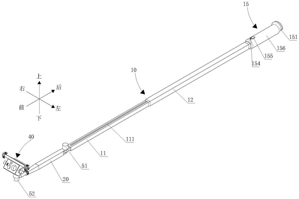
[0032] The up-down, left-right, front-back directions described in the present invention are figure 1 up and down, left and right, and front and back directions.

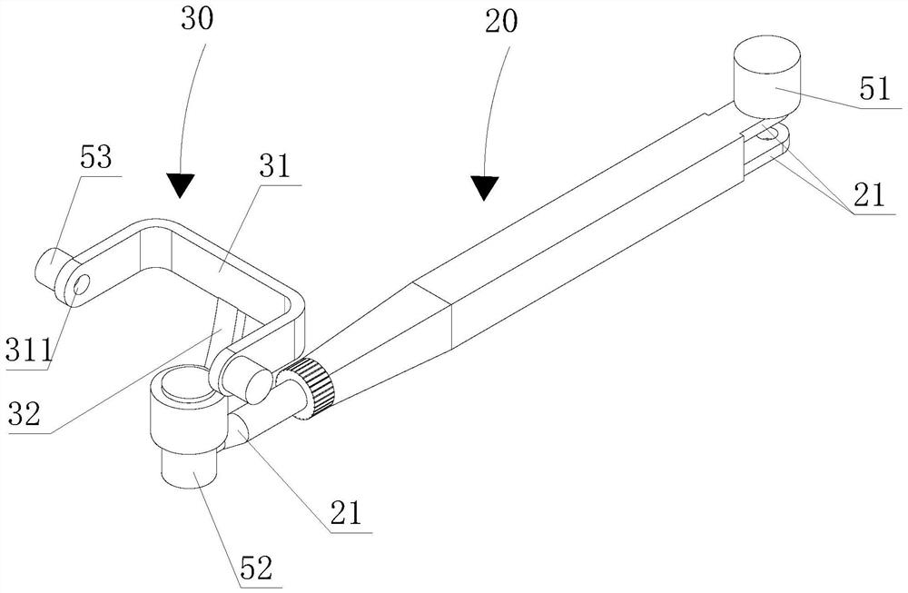
[0033] Such as Figure 1-6 As shown, the nuclear power equipment pipeline inspection device provided by the present invention includes: a telescopic rod 10, a steering rod 20, a pan platform 30, and a lens module 40, wherein the telescopic rod 10 can expand and contract along its own axial direction, and the steering rod 20 Rotationally connected to the front end of the telescopic rod 10, the pan platform 30 is rotatably connected to the front end of the steering rod 20, and the lens ...


PUM


Abstract

The invention provides a nuclear power equipment pipeline inspection device which comprises a telescopic rod capable of stretching out and drawing back in the axis direction of the telescopic rod, a steering rod rotationally connected to the end of the telescopic rod, a holder rotationally connected to the end, away from the telescopic rod, of the steering rod, and a lens module rotationally connected to the holder. The rotation axis of the steering rod, the axis of the telescopic rod and the rotation axis of the lens module are perpendicular to each other, and the rotation axis of the holder is parallel to the rotation axis of the steering rod, so that the lens module can be sent to the position close to the turning part of the to-be-detected pipeline through telescoping of the telescopic rod; the lens module can be sent into the turning part of the to-be-detected pipeline through rotation of the rotating rod and telescopic cooperation of the telescopic rod, the lens module can be driven to achieve dead-corner-free detection through rotation of the holder and rotation of the lens module, operation is convenient, and the detection efficiency is high; the lens module can be kept in a suspended state by utilizing the rigidity of the telescopic rod, the steering rod and the holder, and the imaging effect is good.

Description

technical field [0001] The application belongs to the technical field of inspection, and in particular relates to a nuclear power equipment pipeline inspection device. Background technique [0002] In the field of nuclear power, after the nuclear power equipment has been in service for a certain period, it is necessary to conduct corrosion inspections on the pipelines of nuclear power equipment. Most of the existing inspection methods are visual inspections. The elbows and tees in the pipeline are relatively concealed, and the pipeline space is narrow, making it difficult for inspectors to enter. Moreover, the pipeline environment in some areas is unknown, and rashly entering by force is likely to cause damage to the health of inspectors, making it difficult for inspectors to enter. Carry out a comprehensive and complete inspection of the pipelines of nuclear power equipment, there are inspection dead ends, and there may be corrosion hazards or other defects that affect the ...

Claims


Application Information

Patent Timeline
Patent Type & Authority Applications(China)
IPC IPC(8): G21C17/017
CPCY02E30/30
Inventor 刘洪群张彦召张舟永刘忠潘姚凡
Owner SUZHOU NUCLEAR POWER RES INST
Why Eureka
Try Eureka