Underground passage supporting structure for underneath passing existing large-section shallow-buried pipe gallery and construction method

A technology for underground passages and supporting structures, which is applied to underwater structures, infrastructure engineering, artificial islands, etc., can solve problems such as affecting the normal use of pipelines inside the pipe gallery, instability during excavation, and failure to meet the conditions for undercutting. , to achieve the effect of good promotion and application prospect, simple construction operation and good implementability

Pending Publication Date: 2022-04-12
CHINA RAILWAY LIUYUAN GRP CO LTD +2
View PDF0 Cites 1 Cited by
  • Summary
  • Abstract
  • Description
  • Claims
  • Application Information

AI Technical Summary

Problems solved by technology

[0003] Most of the existing pipe galleries are constructed by the open-cut method, and the buried depth is shallow. The underground passage structure often needs to pass through the pipe gallery structure. The net distance between the two is small, which does not meet the conditions for underground excavation; fast pass
Due to the large cross-sectional area of ​​most pipe galleries and the large number of internal pipelines, there are risks of instability and inclination during the excavation process, which may easily cause settlement of the pipe gallery and structural cracking, which will affect the normal use of the internal pipelines of the pipe gallery

Method used


Image

  • Underground passage supporting structure for underneath passing existing large-section shallow-buried pipe gallery and construction method
  • Underground passage supporting structure for underneath passing existing large-section shallow-buried pipe gallery and construction method
  • Underground passage supporting structure for underneath passing existing large-section shallow-buried pipe gallery and construction method

Examples


Embodiment Construction

[0036] In order to enable those skilled in the art to better understand the technical solution of the present invention, the present invention will be described in detail below in conjunction with the accompanying drawings and specific embodiments.

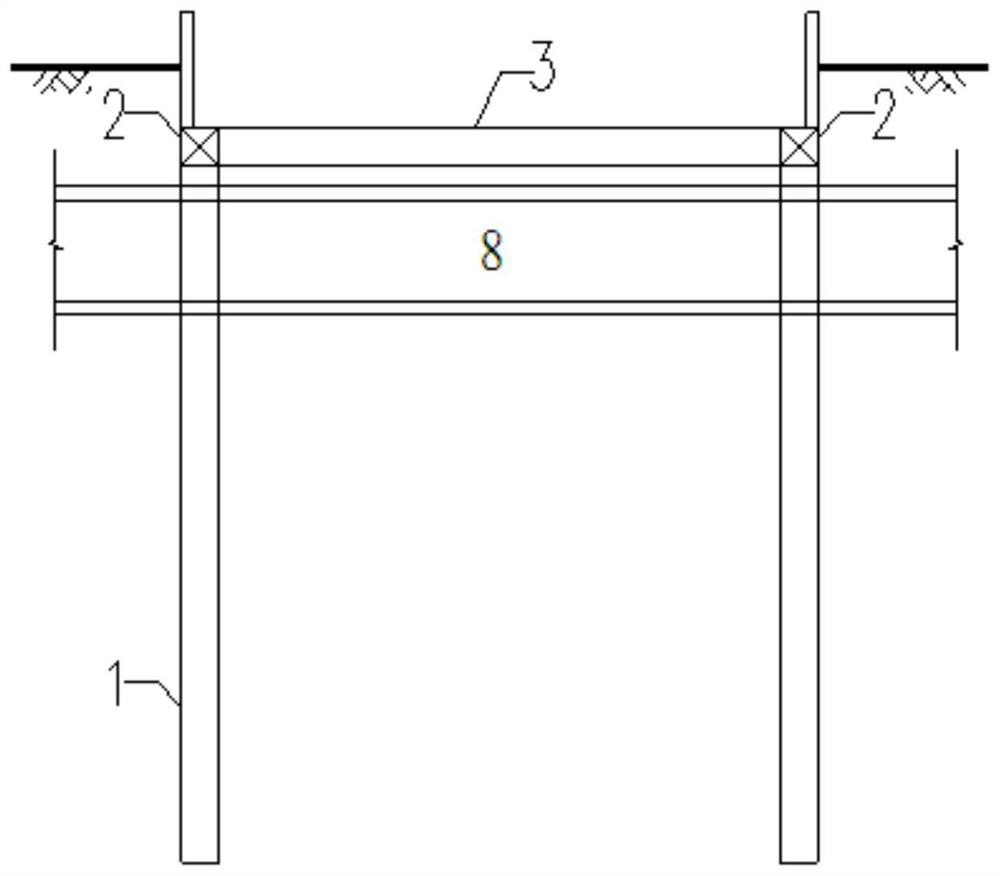
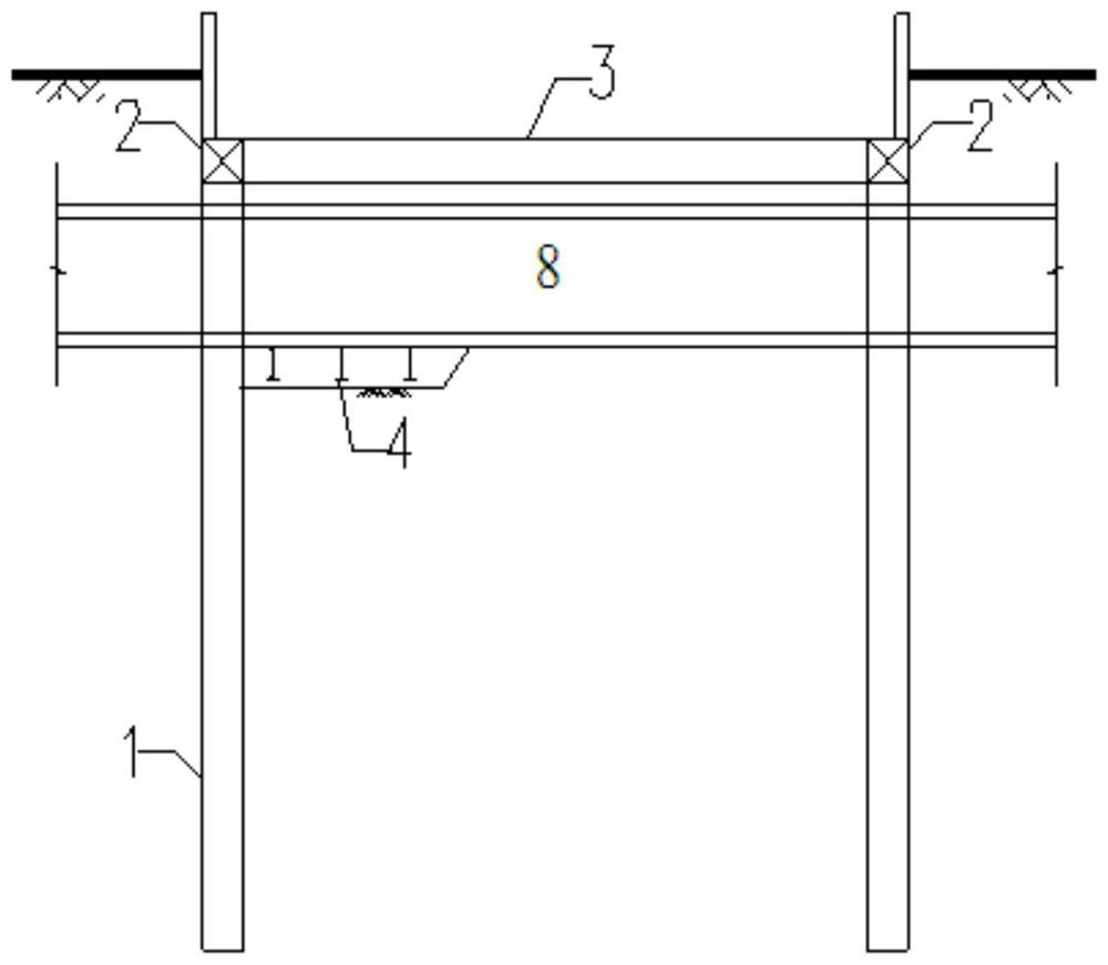
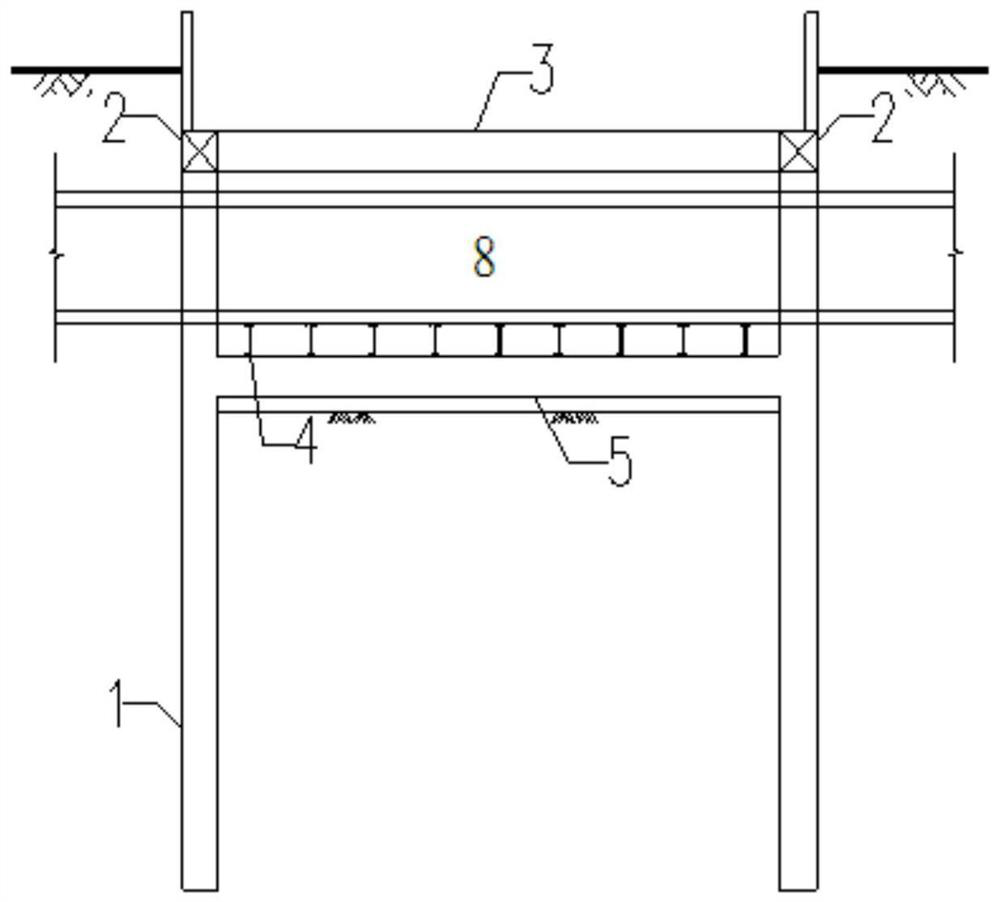
[0037] This embodiment provides an underground passage support structure that passes through the existing large-section shallow-buried pipe gallery, is suitable for the construction of underground passages that pass under the existing large-section shallow-buried pipe gallery, and has the functions of protecting the existing pipe gallery and providing underpass. The role of the channel construction work surface; the support structure of the underground channel under the existing large-section shallow buried pipe gallery in this embodiment is as follows Figure 6 to Figure 8 As shown, it includes bored cast-in-place pile 1, crown beam 2, horizontal concrete support 3, I-beam 4, and concrete support beam 5; bored cast-in-place pile 1...


PUM


Abstract

The invention provides an underground passage supporting structure penetrating an existing large-section shallow-buried pipe gallery downwards and a construction method. Cast-in-situ bored piles are arranged at the four corners of the intersection of the pipe gallery and the underground passage structure in a driving mode, and the tops of the cast-in-situ bored piles on the single side of the underground passage structure are connected through a top beam; the tops of the cast-in-situ bored piles on the two sides of the underground passage structure are connected through transverse concrete supports. A plurality of I-shaped steels are inserted into a soil body below the bottom of the pipe gallery and are attached to the bottom of the pipe gallery; a concrete supporting beam is arranged below the I-shaped steel and attached to the I-shaped steel, the two ends of the concrete supporting beam are connected with the cast-in-situ bored piles on the two sides of the underground passage structure, the underground passage structure is located below the concrete supporting beam, and a gap between the pipe gallery and the underground passage structure is filled with concrete. According to the method, the phenomena of pipe gallery inclination, settlement and structure cracking in the channel undercrossing pipe gallery are avoided, and a safe working face can be provided for undercrossing excavation.

Description

technical field [0001] The invention belongs to the technical field of building structures, and in particular relates to a support structure and a construction method for an underground passage passing through an existing large-section shallow-buried pipe gallery. Background technique [0002] At present, various cities are vigorously carrying out the construction of comprehensive pipe corridors, and each city has built a large number of comprehensive pipe corridors. With the continuous development of underground space, there will inevitably be conflicts between the existing underground pipe gallery structure and the new structure. [0003] Most of the existing pipe galleries are constructed by the open-cut method, and the buried depth is shallow. The underground passage structure often needs to pass through the pipe gallery structure. The net distance between the two is small, which does not meet the conditions for underground excavation; Fast pass. Due to the large cross...

Claims


Application Information

Patent Timeline
IPC IPC(8): E02D29/045E02D5/34E02D29/02
Inventor 毕丽平贺维国刘鹏张建伟孙山尊陈翰吴昊刘世波居多帅顾永财
Owner CHINA RAILWAY LIUYUAN GRP CO LTD
Why Eureka
Try Eureka