Injection mold positioning mechanism

A technology of positioning mechanism and injection mold, which is applied to the separation of dispersed particles, chemical instruments and methods, and filtration of dispersed particles, etc. It can solve the problems of affecting the heat dissipation of the lower mold, without assistance in heat dissipation, and without heat dissipation, so as to achieve flexible use and rapid improvement The effect of cooling molding

Pending Publication Date: 2022-04-12
南京峰晖洛施科技有限公司
View PDF0 Cites 0 Cited by
  • Summary
  • Abstract
  • Description
  • Claims
  • Application Information

AI Technical Summary

Problems solved by technology

[0003] In the process of mold injection molding, the lower mold needs to be positioned. The existing positioning mechanism is usually a structure of a cylinder connected to a splint, which can only be used in the case of clamping a relatively flat side. The shape of the clamped lower mold is limited, and at the same time , does not have the function of heat dissipation. Since the two sides of the lower mold are wrapped when clamping, it will also affect the heat dissipation of the lower mold when clamping. At the same time, there is no effect of assisting heat dissipation. The function is single and only used for the mold. position

Method used


Image

  • Injection mold positioning mechanism
  • Injection mold positioning mechanism
  • Injection mold positioning mechanism

Examples


Embodiment Construction

[0031] The following description serves to disclose the present invention to enable those skilled in the art to carry out the present invention. The preferred embodiments described below are only examples, and those skilled in the art can devise other obvious variations.

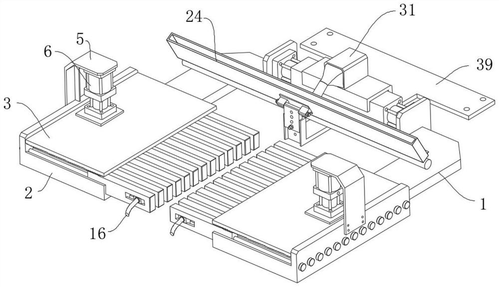
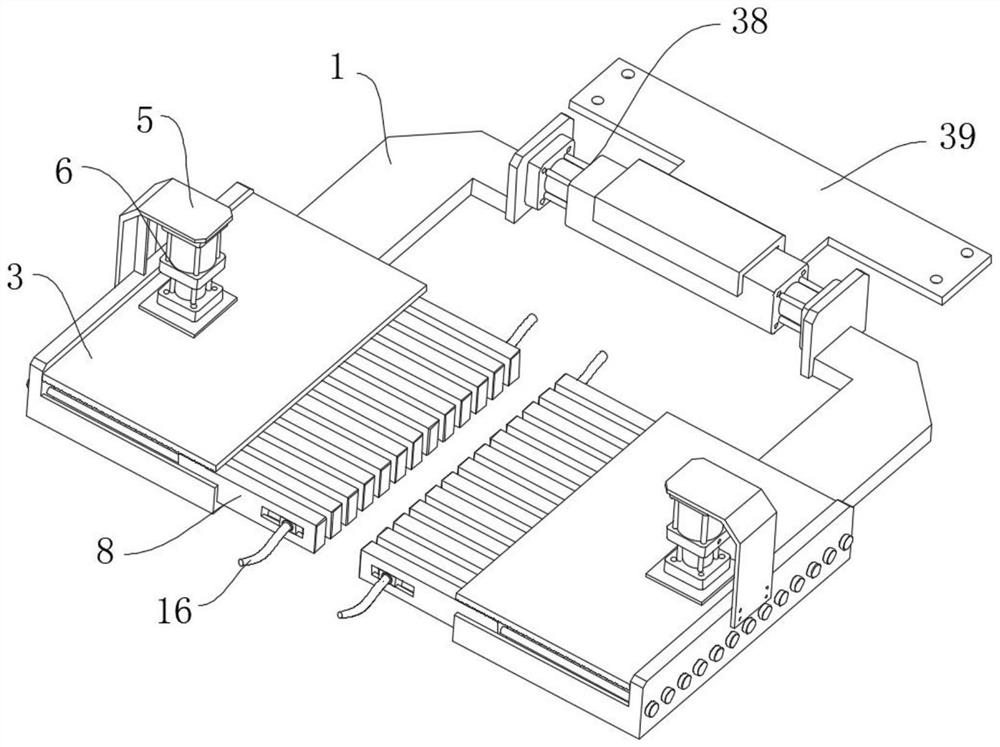
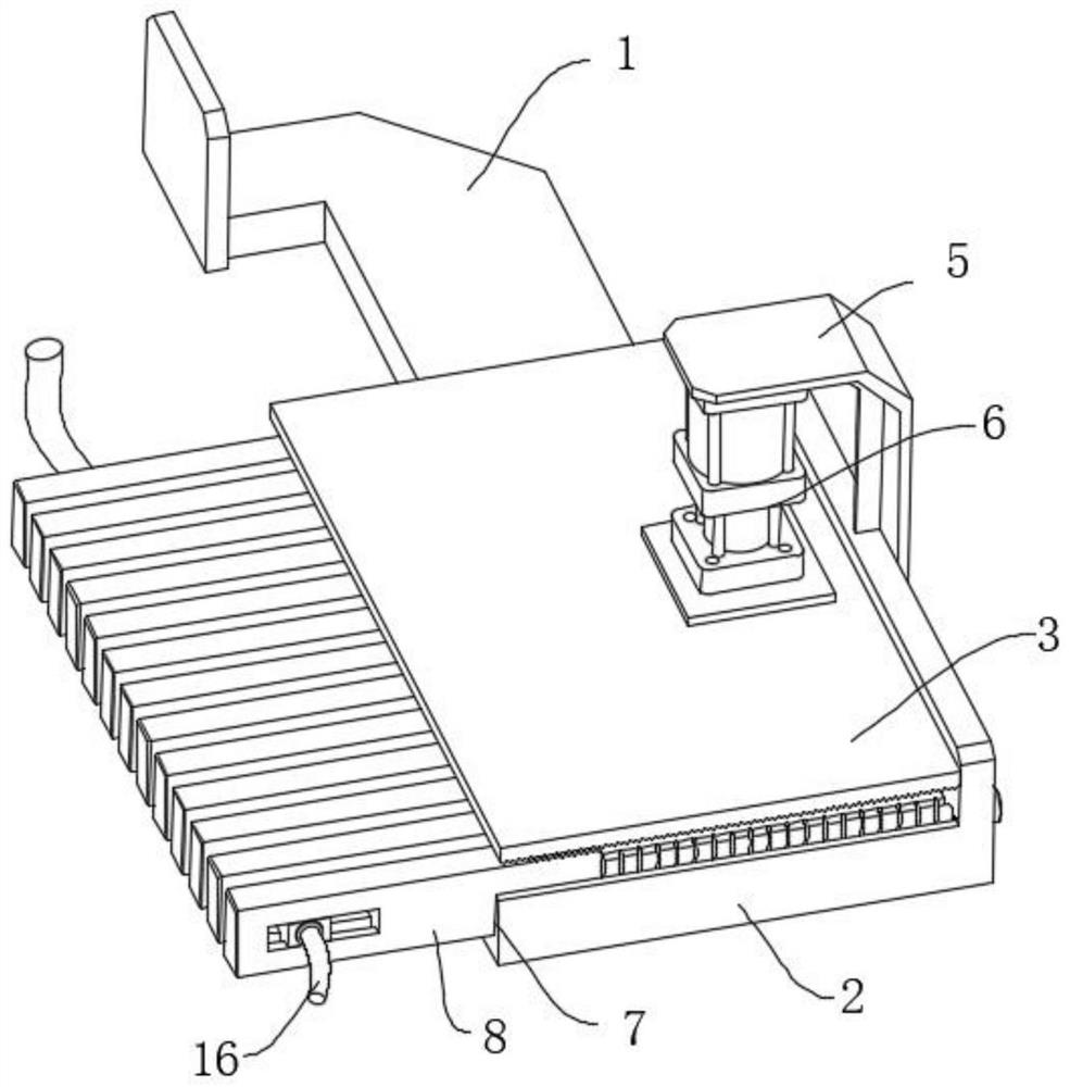
[0032] Such as Figure 1-Figure 10 The injection mold positioning mechanism shown includes a connecting plate 1. The number of connecting plates 1 is set to two and arranged symmetrically. The front end of the base plate 2 is fixedly connected with a base plate 2, and the upper end surface of the base plate 2 is slidably installed with several limit blocks 8 along both sides. An elastic mechanism is arranged between one end of the limit block 8 and the edge of the base plate 2. Pressing plate 3 is installed by lifting mechanism, and lifting mechanism controls pressing plate 3 to move down and press on the surface of limiting block 8 to stabilize limiting block 8, and the front of telescopic mechanism is pro...


PUM


Abstract

The invention relates to the technical field of mold positioning, in particular to an injection mold positioning mechanism which comprises two connecting plates, the two connecting plates are symmetrically arranged, the rear ends of the two connecting plates are controlled to be close to or away from each other through a telescopic mechanism, and the front ends of the connecting plates are fixedly connected with a bottom plate; a plurality of limiting blocks are installed on the upper end face of the bottom plate in the direction of the two sides in a sliding mode, an elastic mechanism is arranged between one end of each limiting block and the edge of the bottom plate, and a pressing plate is installed above the bottom plate through a lifting mechanism. And the contact position with the lower die can absorb heat well, heat dissipation of the lower die is prevented from being affected, and then the cooling forming efficiency of a product is affected, the heat dissipation effect is achieved, dust on the surface of the lower die can be cleaned while heat dissipation is conducted, and the functions are diversified.

Description

technical field [0001] The invention relates to the technical field of mold positioning, in particular to an injection mold positioning mechanism. Background technique [0002] Injection molding, also known as injection molding, is a molding method of injection and molding. The advantages of the injection molding method are fast production speed, high efficiency, automatic operation, various designs and colors, simple to complex shapes, large to small sizes, accurate product sizes, easy replacement of products, and complex shapes. Injection molding is suitable for mass production and complex-shaped products and other molding processing fields. Injection molding requires the use of injection molds. [0003] In the process of mold injection molding, the lower mold needs to be positioned. The existing positioning mechanism is usually a structure of a cylinder connected to a splint, which can only be used in the case of clamping a relatively flat side. The shape of the clamped ...

Claims


Application Information

Patent Timeline
IPC IPC(8): B29C45/17B29C45/73B01D46/10B29C33/30B29C33/72
Inventor 王雪荣
Owner 南京峰晖洛施科技有限公司
Why Eureka
Try Eureka