
Electromagnetic clamp for clamping cylinder sleeve

A technology of electromagnetic fixtures and cylinder liners, which is applied in the direction of workpiece clamping devices and manufacturing tools, can solve problems such as difficult flexible control of fixtures, complex structures, and deformation of cylinder liners, and achieve low manufacturing costs, simple structures, and flexible control.

Active Publication Date: 2022-04-12
NANJING UNIV OF AERONAUTICS & ASTRONAUTICS
View PDF9 Cites 0 Cited by
  • Summary
  • Abstract
  • Description
  • Claims
  • Application Information

AI Technical Summary

Problems solved by technology

[0007] The object of the present invention is to design a cylinder liner electromagnetic clamp with simple structure, strong applicability, flexible control and long service life, aiming at the problem that the existing cylinder liner fixture has complex structure and uneven force is easy to cause deformation of the cylinder liner. Solve the problems that the contact area between the clamping element and the cylinder liner of the existing cylinder liner fixture is small, the clamping force is unevenly distributed, and the fixture is difficult to control flexibly

Method used


Image

  • Electromagnetic clamp for clamping cylinder sleeve
  • Electromagnetic clamp for clamping cylinder sleeve
  • Electromagnetic clamp for clamping cylinder sleeve

Examples


Embodiment Construction

[0025] The present invention will be further described below with reference to the accompanying drawings and examples.

[0026] Such as Figure 1-4 Indicated.

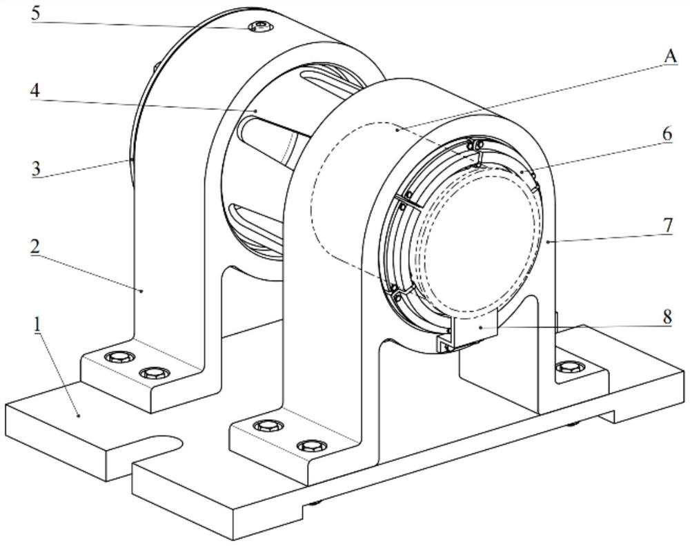
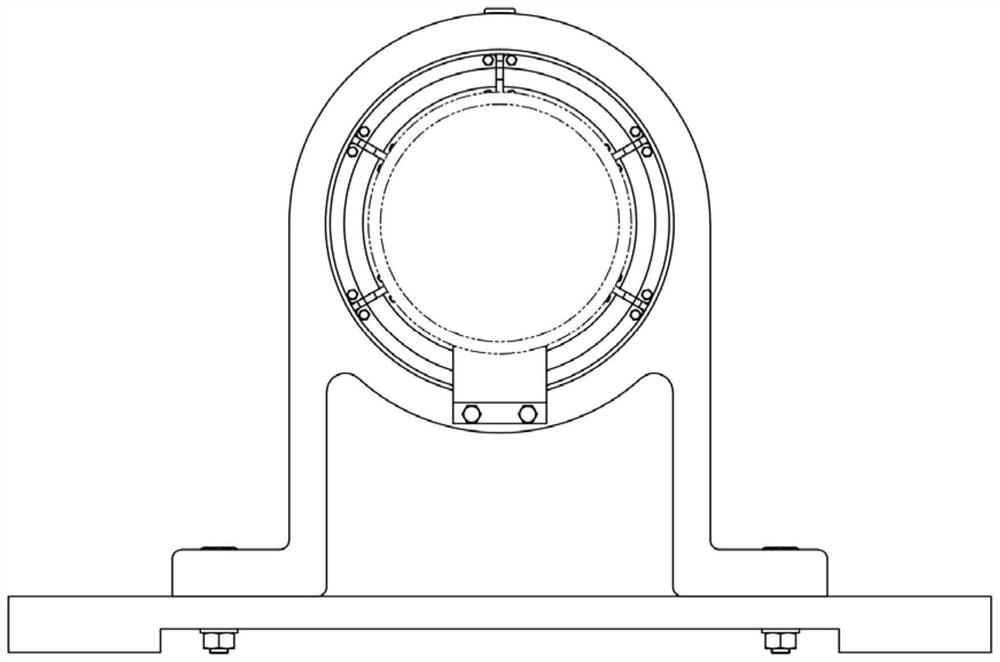
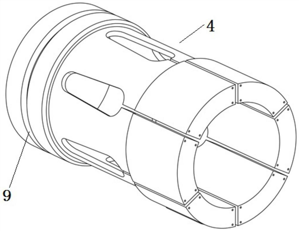
[0027] A electromagnetic clamp holding a cylinder liner comprising: a base 1, a base 1 having two supports, and the base 1 and the first support 2, the second support 7 connecting positions have a U-hole, For the mounting position of the mount; the first branch 2 end surface ( figure 2 ) And upper surface ( figure 1 It is provided with a threaded hole for mounting the end cap 3 and the lock screw 5, the end cap 3 and the lock screw 5 are used to fix clamping chuck 4, clamping the collet 4 end surface is connected to the package coil 6; second The seat 7 end surface is connected to the finite plate 8, and the limit panel 8 is used to ensure the consistency of the position of the cylinder block A. figure 1 Indicated.

[0028] Specifically, the clamping tape 4 side circumferential surface is provided with a trapezoidal groove ...


PUM


Abstract

An electromagnetic clamp for clamping an air cylinder sleeve is characterized by comprising a base, two supports are fixedly connected to the upper surface of the base, threaded holes are formed in the end face and the upper surface of the first support and used for installing an end cover and a locking screw, the end cover and the locking screw are used for fixing a clamping chuck, the clamping chuck is provided with grooves which are evenly distributed in the circumferential direction, and the grooves are used for clamping the air cylinder sleeve. End faces of the coils are connected with packaging coils, the packaging coils are evenly distributed in the circumferential direction, and arc-shaped iron cores are arranged in the packaging coils. The end face of the second support is connected with a limiting plate, and the limiting plate is used for guaranteeing the consistency of the air cylinder sleeving and clamping positions. By changing the current direction in the coil, clamping of the inner hole and the outer circle of the cylinder sleeve can be achieved, by changing the current magnitude, the clamping force can be adjusted, and the clamping device is simple in structure, long in service life, high in applicability and low in manufacturing cost.

Description

Technical field [0001] The present invention relates to an electric clamp technology, in particular a high-precision cylinder set or an outer clamping apparatus, specifically a electromagnetic clamp holding a cylinder liner. Background technique [0002] The cylindercloth is a key part of the engine for the engine's core power assembly, which determines the service life of the engine. Therefore, the development and preparation of high-performance cylindernets have important strategic significance. [0003] Chinese patent released a cylinder block clamp (public number: CN107900746A), including: base, first, second swing mechanism, and synchronous drive, wherein the first swing mechanism has a first V-type positioning portion, and its swing axis is parallel Cylinder blocks; the second swing mechanism provides a second V-type positioning unit; the synchronous drive is used to simultaneously drive the first swing mechanism and the second swing mechanism to move the two swing mechanis...

Claims


Application Information

Patent Timeline
IPC IPC(8): B25B11/00
Inventor 徐锋周潜赵文轩徐吉赵延超高承钻左敦稳
Owner NANJING UNIV OF AERONAUTICS & ASTRONAUTICS
Learn More