
Mechanical manufacturing stamping device

A punching device and machine manufacturing technology, applied in the field of mechanical punching, can solve the problems of inconvenient pressure application, poor punching effect, accidental injury, etc.

Pending Publication Date: 2022-04-12
时浩章
View PDF5 Cites 0 Cited by
  • Summary
  • Abstract
  • Description
  • Claims
  • Application Information

AI Technical Summary

Problems solved by technology

[0004] 1. Stamping equipment that relies on manpower to apply pressure is not convenient enough to apply pressure, and the effect of manpower into pressure is poor, resulting in time-consuming and laborious, and the effect of stamping is poor;
[0005] 2. Most of the small stamping equipment rely on manual placement and removal of stamping parts, and in the process of taking and placing stamping parts, it is easy to cause accidental injury;
[0006] 3. It is inconvenient to take out the parts after stamping;

Method used


Image

  • Mechanical manufacturing stamping device
  • Mechanical manufacturing stamping device
  • Mechanical manufacturing stamping device

Examples


Embodiment

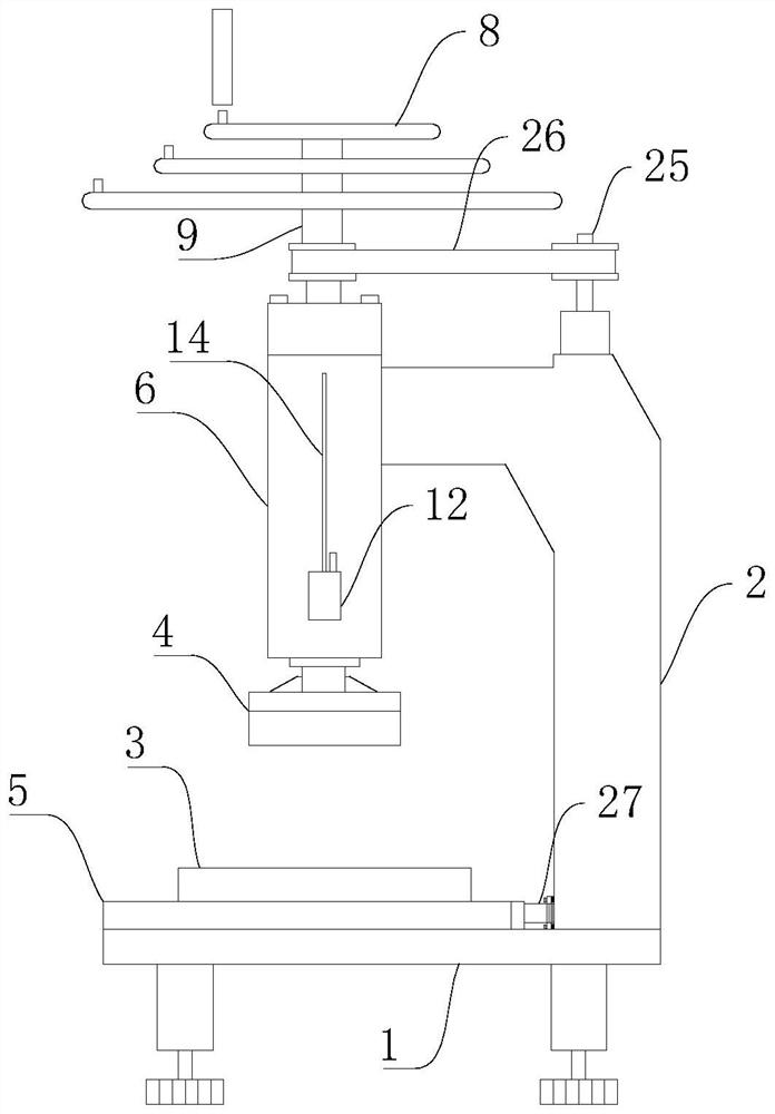
[0049] Please refer to Figure 1-Figure 8 , figure 1 Shown is a schematic structural view of one of the stamping components in the embodiment of the present invention;

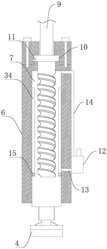
[0050] figure 2 Shown is a schematic diagram of the connection of the installation sleeve 6, the connecting shaft 9 and the stamping rod 7 in the embodiment of the present invention;

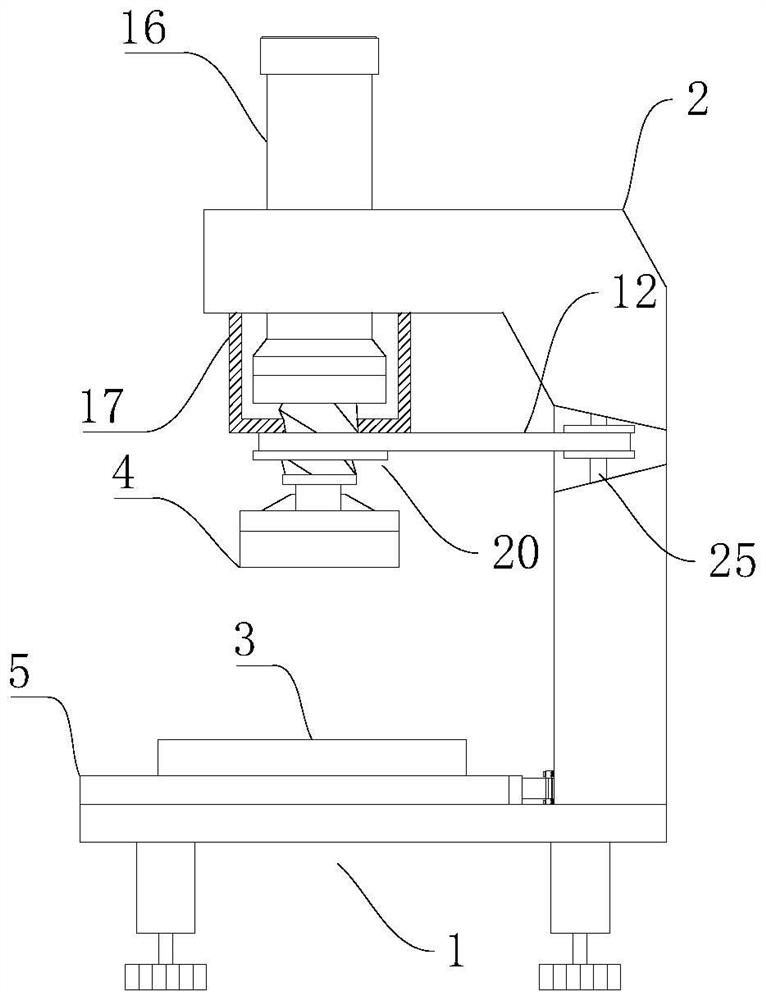
[0051] image 3 Shown is a schematic structural view of another stamping assembly in the embodiment of the present invention;

[0052] Figure 4 Shown is a schematic structural view of the output end of the hydraulic push rod 16 in the embodiment of the present invention;

[0053] Figure 5 Shown is a schematic structural diagram of the through hole 19 in the embodiment of the present invention;

[0054] Image 6 Shown is a schematic diagram of the installation of the linkage assembly in the embodiment of the present invention;

[0055] Figure 7 shown as Image 6 The enlarged schematic diagram of A in the middle;

...


PUM


Abstract

The invention provides a mechanical manufacturing stamping device, and relates to the technical field of mechanical stamping. Comprising a stamping assembly and a mounting base, the stamping assembly is erected above the mounting base through a supporting arm, a sliding platform is arranged on the upper end face of the mounting base, the sliding platform and the stamping assembly are connected through a linkage assembly, and the linkage assembly can enable the acting end of the stamping assembly to move downwards. The sliding platform horizontally moves on the upper end face of the mounting base, and when the sliding platform moves to the maximum distance away from the mounting base, the stamping die is enough to be separated from the lower area of the stamping assembly; when manual stamping is carried out, manpower can be converted into stamping pressure to the maximum extent, so that the labor intensity of workers is reduced, and the stamping effect is improved; and in the process of taking and placing the stamped parts, accidental injury to personnel can be avoided, meanwhile, stamped equipment can be easily taken out, and therefore the whole device has higher practicability, flexibility and safety in the using process.

Description

technical field [0001] The invention relates to the technical field of mechanical stamping, in particular to a stamping device for mechanical manufacturing. Background technique [0002] Stamping is a processing method that applies external force to plates, strips, pipes, and profiles by pressure and molds to cause plastic deformation or separation to obtain workpieces (stampings) of required shape and size. Method; Compared with castings and forgings, stamping parts have the characteristics of thinness, uniformity, lightness and strength. Stamping can produce workpieces with ribs, ribs, undulations or flanges that are difficult to manufacture by other methods to increase their rigidity. [0003] For stamping, there are relatively large stamping equipment, and there are also small stamping equipment. Large stamping equipment usually uses a press to apply pressure. Some small stamping equipment rely on simple stamping by manpower, and some rely on hydraulic push rods to appl...

Claims


Application Information

Patent Timeline
Patent Type & Authority Applications(China)
IPC IPC(8): B21D22/02B21D37/04B21D37/18B21D55/00
Inventor 时浩章姚忠国王立娟刘洋
Owner 时浩章
Learn More