Motor drive control device and method for controlling motor drive control device
A motor drive control and motor drive technology, which is applied in the direction of rotation direction control, electronic commutator, etc., can solve the problems of difficult zero-cross detection, estimation of rotation direction, etc., and achieve the effect of simple structure
- Summary
- Abstract
- Description
- Claims
- Application Information
AI Technical Summary
Problems solved by technology
Method used
Image

Examples
no. 1 approach
[0043] First, the motor drive control device and the control method of the motor drive control device according to the first embodiment will be described.
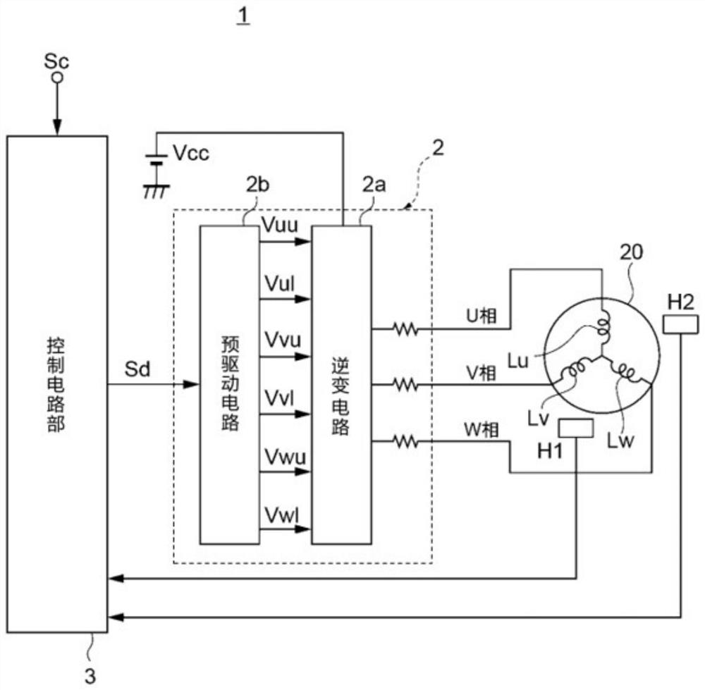
[0044] figure 1 It is a diagram roughly showing the circuit configuration of the motor drive control device 1 according to the first embodiment.
[0045] The motor drive control device 1 drives the motor 20 . In this embodiment, the motor 20 is, for example, a three-phase brushless motor. The motor drive control device 1 rotates the motor 20 by periodically passing a drive current to the armature coils Lu, Lv, and Lw of the motor 20 .
[0046] The motor drive control device 1 has a motor drive unit 2, a control circuit unit 3, a first Hall element H1, and a second Hall element H2 (H1 and H2 are sometimes simply referred to as Hall elements). also, figure 1 The components of the shown motor drive control device 1 are part of the whole, and the motor drive control device 1 is in figure 1 In addition to the components sh...
no. 2 approach
[0084] Next, the motor drive control device and the control method of the motor drive control device according to the second embodiment will be described.
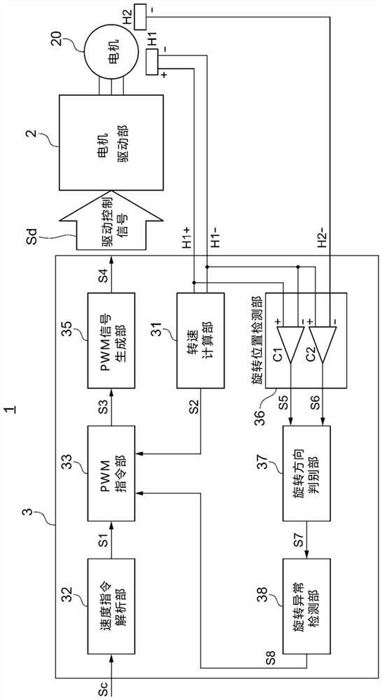
[0085] Figure 8 It is a block diagram showing the configuration of the control circuit unit 3A of the second embodiment.
[0086] In the motor drive control device 1 of the first embodiment, the Hall signal H1 is input to the rotational position detection unit 36 . + 、H1 - , H2 - , and in the motor drive control device 1A of this embodiment, the difference lies in that Figure 8 As shown, in addition to the input Hall signal H1 in the rotation position detection part 36 + 、H1 - , H2- In addition, a reference voltage having a predetermined potential (an example of a comparison signal to be compared) is also input. In addition, the difference is that the rotation direction determination unit 37A compares the variation of the first position detection signal S5 and the variation of the second position detection signal...
no. 3 approach
[0096] Next, the motor drive control device and the control method of the motor drive control device according to the third embodiment will be described.
[0097] Figure 11 It is a block diagram showing the configuration of the control circuit unit 3B of the third embodiment.
[0098] In the motor drive control devices 1 and 1A of the above-described embodiments, one of the first position detection signal S5 and the second position detection signal S6 received from the rotational position detection unit 36 by the rotation direction determination units 37 and 37A is When the output of the output changes, according to the direction of the change (from "0" to "1", or from "1" to "0"), and another position detection signal S5 or The comparison result of the output of S6 (whether it is "0" or "1") determines the rotation direction of the motor. In the motor drive control device 1B of the present embodiment, the rotation direction determination unit 37B compares the variation o...
PUM
 Abstract
Description
Claims
Application Information
 - R&D
- Intellectual Property
- Life Sciences
- Materials
- Tech Scout
- Unparalleled Data Quality
- Higher Quality Content
- 60% Fewer Hallucinations
Browse by: Latest US Patents, China's latest patents, Technical Efficacy Thesaurus, Application Domain, Technology Topic, Popular Technical Reports.
© 2025 PatSnap. All rights reserved.Legal|Privacy policy|Modern Slavery Act Transparency Statement|Sitemap|About US| Contact US: help@patsnap.com