Water meter sensing device

A water meter and sensing technology, applied in the field of meters, can solve the problems of high cost, complex structure, difficult preparation process, etc., and achieve the effect of simple installation

Inactive Publication Date: 2017-05-17
尤世元
View PDF0 Cites 0 Cited by
  • Summary
  • Abstract
  • Description
  • Claims
  • Application Information

AI Technical Summary

Problems solved by technology

[0004] The existing water meter sensing devices mostly use magnetic sensing devices such as spring tubes. Therefore, it is inevitable to have inherent defects and drawbacks of magnetic sensing devices. For example, when there is a strong magnetic field interference from the outside, the magnetic sensing The state of the device will be locked and invalidated; in a high humidity environment, the magnetic sensing device will rust and its magnetism will drop until it is completely demagnetized
In order to solve these problems existing in the magnetic sensing device, there are many examples of using photoelectric water meter sensing device at present, but its main structure and characteristics are: 5 reflective surfaces are set on the circumference of each water meter character wheel , set 5 photocouplers at the corresponding positions to form 5 pairs of sensing devices, and determine the position of the counting wheel through the reflection of the coupler. Install sensing devices on top; for example: to read 5 digits, install 5×5=25 pairs of sensing devices. This kind of direct-reading sensing device water meter is generally only suitable for It is suitable for dry water meter series, and its structure is complex, the preparation process is difficult, the cost is high, the service life is short, and the use range is limited by the measured liquid

Method used


Image

  • Water meter sensing device
  • Water meter sensing device

Examples


Embodiment 1

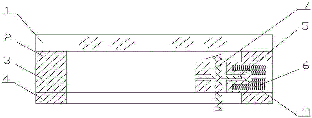
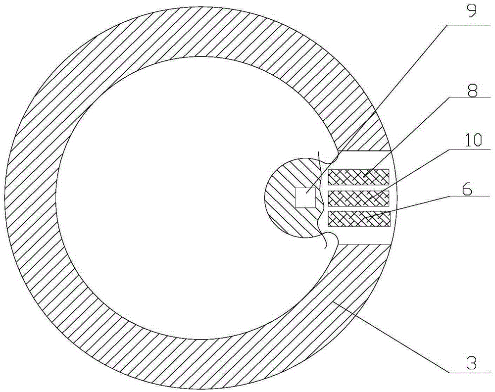
[0015] In this embodiment, three groups of photoelectric coupling sensor devices are installed or refitted in the water meter of the existing structure, and the structure of the water meter and its sensor device fixed body consists of: observation window glass 1, rubber sealing gasket 2, sensor device fixing Body 3, waterproof rubber gasket 4, semicircular shading plate 5, photoelectric coupling sensing device 6, 8 and 10, turntable pointer 7, turntable pointer axis 9 and slot 11; observation window glass 1 and waterproof rubber sealing ring 4 A sensing device fixed body 3 made of light-transmitting material and a rubber sealing gasket 2 are installed between them, and a semicircular light-shielding plate 5 is installed on one of the turntable pointers 7 of the water meter and inserted into the axis 9 of the turntable pointer to prevent light The board 5 is embedded in the slot 11 in the fixed body of the sensing device, and three sets of photoelectric devices matching the emis...


PUM


Abstract

The invention relates to a water meter sensing device. The water meter sensing device is a annular integrated device which is made by pressing transparent materials, the size of the water meter sensing device is the same as that of a viewing glass frame of an existing refitted water meter, the position, corresponding to a water meter turnplate pointer, of the ring body, is provided with a poroid turnplate pointer axis, the position, corresponding to a semicircle-shaped light-shielding plate is provided with a slot, the upper side and the lower side of the slot are provided with two or three sets of photoelectric devices which are used for emitting and receiving pairs respectively, and the photoelectric devices are embedded in a sensor fixed body in a circular annular shape, the fixed body is sealed and additionally arranged between the viewing glass of the water meter and a waterproof rubber gasket, and the photoelectric devices continuously output high and low level signals at uniform intervals so as to be used for metering equipment when the water meter drives the light-shielding plate to rotate. The water meter sensing device is simple in principle structure, and safe and reliable to install and use; meanwhile, needs of an existing water meter for information metering can be met, and refitting of the current situation of the existing water meter is promoted.

Description

[0001] Technical field: [0002] The invention belongs to the technical field of meters, and relates to a counting device suitable for measuring flow in liquid flow occasions, in particular to a water meter sensing device. [0003] technical background: [0004] The existing water meter sensing devices mostly use magnetic sensing devices such as spring tubes. Therefore, it is inevitable to have inherent defects and drawbacks of magnetic sensing devices. For example, when there is a strong magnetic field interference from the outside, the magnetic sensing The state of the device will be locked and become invalid; in a high humidity environment, the magnetic sensing device will be rusted, and the magnetism will drop until it is completely demagnetized. In order to solve these problems existing in the magnetic sensing device, there are many examples of using photoelectric water meter sensing device at present, but its main structure and characteristics are: 5 reflective surfaces a...

Claims


Application Information

Patent Timeline
Patent Type & Authority Applications(China)
IPC IPC(8): G01F15/00G01F15/07
Inventor 孙波孙亮
Owner 尤世元
Why Eureka
Try Eureka