An Angle Measuring Method for Construction Machinery

A technology for angle measurement and construction machinery, which is applied to mechanically driven excavators/dredgers, measuring devices, and electrical devices, and can solve problems such as easy damage to connecting rods

Active Publication Date: 2018-09-25
江苏泽佳建设有限公司
View PDF2 Cites 0 Cited by
  • Summary
  • Abstract
  • Description
  • Claims
  • Application Information

AI Technical Summary

Problems solved by technology

[0006] However, the problem with the above solutions is that they all need to use connecting rods to transmit the movement angle, and due to the frequent movement and the harsh working environment of construction machinery, the exposed connecting rods are easily damaged, thus requiring frequent replacement

Method used


Image

  • An Angle Measuring Method for Construction Machinery
  • An Angle Measuring Method for Construction Machinery

Examples


Embodiment 1

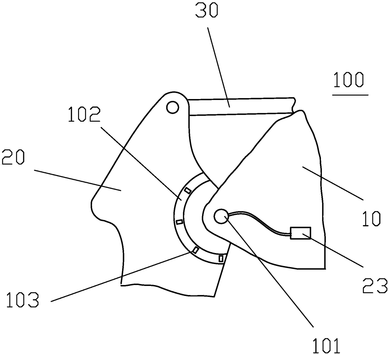
[0025] The present invention provides an angle sensor 100 for a construction machine, which is illustrated as an angle sensor installed between the boom 10 and the stick 20 .

[0026] During working, the arm 20 can pivot around the pin 101 of the boom 10 under the action of the hydraulic lever 30 . The angle measuring device 100 includes an arc-shaped annular magnet seat 102 , which is arranged on the stick 20 and distributed around the pin shaft 101 in a ring shape. Preferably, the annular magnet seat 102 is arranged inside the box-shaped structure of the stick 20 to protect the annular magnet seat 102 from collision damage during operation. However, the present invention is not limited thereto, and the annular magnet seat 102 can obviously also be arranged outside the stick 20 . Schematic figure 1 There is a relatively large distance between the middle annular magnet seat 102 and the pin shaft 101 , but the present invention does not limit the distance.

[0027] The end o...

Embodiment 2

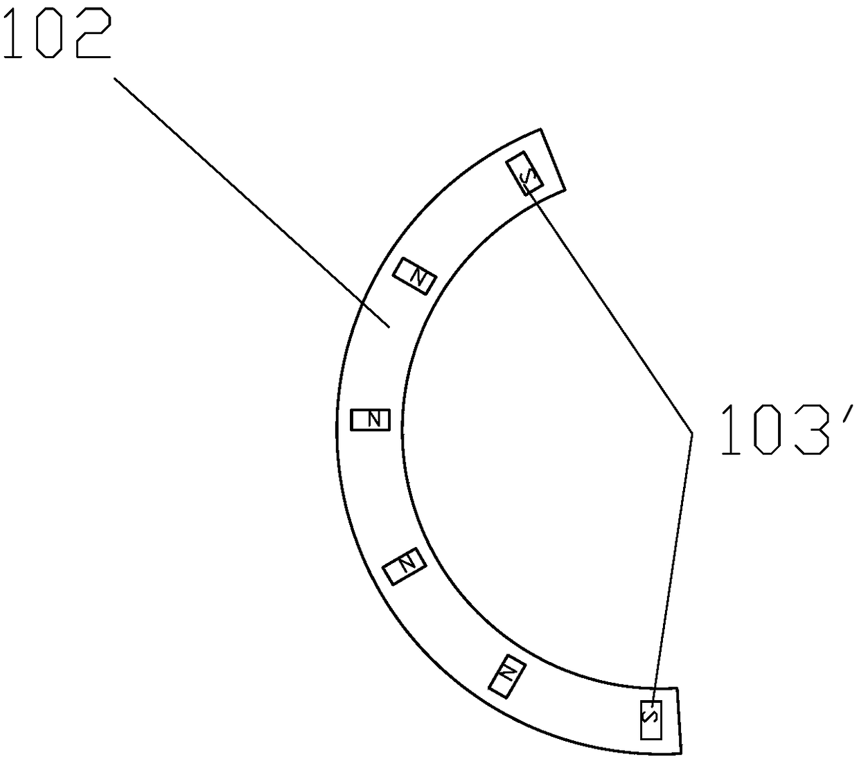
[0030] Preferably, the annular magnet base 102 includes a plurality of magnets 103 arranged around the pin shaft 101, so that the magnetic flux measured by the Hall effect sensor is more obvious. Such as figure 2 As shown, the magnetic poles of the magnets 103 arranged at the arc-shaped two ends of the ring-shaped magnet base 102 magnets are opposite to the other magnetic poles. In this way, when the arm rotates, when the magnetic field strength detected by the Hall effect sensor changes abruptly, it can Mutation of the trigger signal.

[0031] Preferably, the number of Hall switches arranged on the circuit board is n, and n is a natural number, which corresponds to the angle along the ring magnet base 102. Therefore, when the stick 10 rotates and triggers m switches, the circuit corresponds to Generate m fixed codes, each of which contains two sets of data (because only the magnetic poles of the magnets 103' at both ends are different), where m is less than n, and only need...


PUM


Abstract

The invention discloses an angle sensing device of building machinery and an angle measuring method. The angle sensing device comprises an arched annular magnet base and a pin shaft, and is characterized in that the arched annular magnet base is distributed around the pin shaft; a Hall effect sensor is arranged in the end part of the pin shaft, and is a Hall chip mounted on a circuit board; the circuit board is connected to a signal sending / receiving machine through a connecting wire; and magnetic poles of magnets arranged at two arc end parts of the annular magnet base are opposite to a magnetic pole of a magnet arranged in the arc middle position of the annular magnet base.

Description

technical field [0001] The invention relates to the field of construction machinery, in particular to an angle measurement method for construction machinery. Background technique [0002] In construction machinery, operating devices such as buckets, grabs, etc. are usually coupled to the cantilever, and the coupled working accessories often need to move left and right or up and down during the working process. In order to prevent the range of the working device from being too large, or for the sake of operation automation, it is necessary to detect the movement angle between the boom, stick, or bucket and other components. [0003] Angle sensors attached to these components are often used in the field, and these components usually have components such as a rotation angle detection component, a sensor body, and a swing rod for transmitting a motion angle. [0004] For example, Chinese patent CN103669442A discloses an angle detection device for construction machinery, which i...

Claims


Application Information

Patent Timeline
Patent Type & Authority Patents(China)
IPC IPC(8): E02F3/43G01B7/30
CPCE02F3/43G01B7/30
Inventor 华若延
Owner 江苏泽佳建设有限公司
Why Eureka
Try Eureka