Portable power box based on photovoltaic power generation
A photovoltaic power generation and power box technology, applied in the field of power boxes, can solve the problems of dust accumulation at the seams, adjusting the handle, slung on the body, etc., to achieve the effects of increasing power generation, flexible use, and improving power generation efficiency
- Summary
- Abstract
- Description
- Claims
- Application Information
AI Technical Summary
Problems solved by technology
Method used
Image
Examples
Embodiment 1
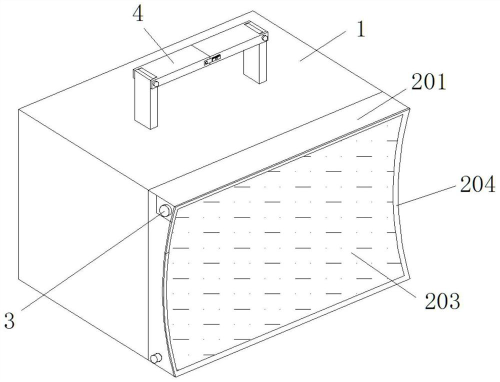
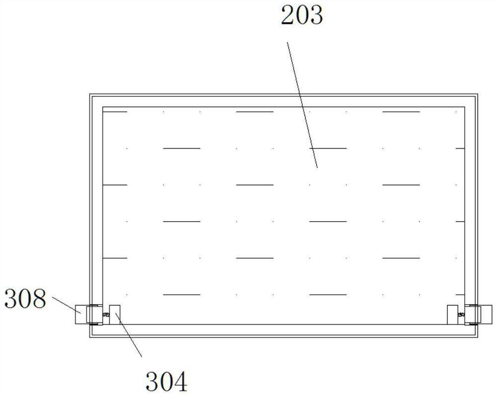
[0031] see Figure 1-8 , the present invention provides a technical solution: a portable portable power box based on photovoltaic power generation, including a power box body 1, a photovoltaic power generation mechanism 2, an opening and closing mechanism 3, a portable mechanism 4 and a sling mechanism 5, and the photovoltaic power generation mechanism 2 is located The front end of the power box body 1, the opening and closing mechanism 3 is located at the outer end of the photovoltaic power generation mechanism 2, the portable mechanism 4 is located at the upper end of the power box body 1, and the oblique mechanism 5 is located inside the portable mechanism 4;
[0032] The photovoltaic power generation mechanism 2 includes a side plate 201, an insulating cover 202, a flexible photovoltaic power generation panel 203 and a concave mirror 204. The side plate 201 is fixedly installed on the outer end of the power box body 1, and the insulating cover 202 is movably installed on th...
Embodiment 2
[0037] see Figure 1-8 The portable mechanism 4 includes a support rod 401, a left movable rod 402, a right movable rod 403, a buckle plate 404, a limit groove 405, a pressure groove 406, a third spring 407, a connecting block 408, a damping rotating shaft 409, a limit plate 410, Support plate 411, pressing plate 412, the 3rd expansion link 413 and the 4th spring 414, support bar 401 is fixedly installed on the left and right sides of power box body 1 upper end, and left movable bar 402 is installed on the left side of support bar 401 upper end movably, right The movable rod 403 is movably installed on the right side of the upper end of the support rod 401, the buckle 404 is movably installed at the front and rear ends of the left movable rod 402, the limit groove 405 is fixedly arranged on the outer end of the buckle 404, and the pressure groove 406 is fixedly arranged on the buckle. The upper and lower ends of the plate 404, by setting the buckle plate 404, can conveniently ...
PUM
 Abstract
Description
Claims
Application Information
 - R&D
- Intellectual Property
- Life Sciences
- Materials
- Tech Scout
- Unparalleled Data Quality
- Higher Quality Content
- 60% Fewer Hallucinations
Browse by: Latest US Patents, China's latest patents, Technical Efficacy Thesaurus, Application Domain, Technology Topic, Popular Technical Reports.
© 2025 PatSnap. All rights reserved.Legal|Privacy policy|Modern Slavery Act Transparency Statement|Sitemap|About US| Contact US: help@patsnap.com


