
Patsnap Eureka
For R&D, Patsnap Eureka makes reading and utilizing patents & technical documents easy.
Patsnap Eureka AIR
Designed for self-driven R&D workflows. Generate viable solutions, solve complex R&D challenges, empower your innovation with AI.

Patsnap Eureka Materials
Designed for material experts only. Revolutionize your material R&D, from search, analyze, to developing new materials.

TechResearch
Generate reliable direction feasibility study reports for your R&D in just a few steps.

TechSeek
Discover and master advanced knowledge NOW. Basics, ideas, possibilities, all at once.

TechMind
As an expert in R&D Theories, TechMind can generates customized viable solutions instantly.

TechRisk
Analyze your overall solution with one click, know your potential R&D risks in advance.

TechMonitor
Get weekly tech updates, stay abreast of the latest tech innovations and key insights.
Common mode choke
A common mode choke coil and wire technology, which is applied in the field of improvement of winding methods, can solve the problems of inability to obtain characteristics, inability to reduce mode conversion characteristics, etc., and achieve the effect of balancing inductance components
- Summary
- Abstract
- Description
- Claims
- Application Information
AI Technical Summary
Problems solved by technology
Method used
Image


Examples
no. 1 approach
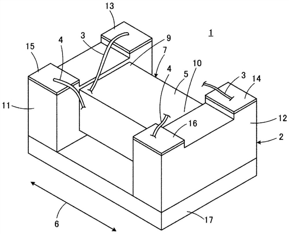
[0040] figure 1 The appearance of the common mode choke coil 1 according to the first embodiment of the present invention is shown.
[0041] The common mode choke coil 1 is provided with the magnetic core 2, the 1st lead wire 3, and the 2nd lead wire 4 which respectively comprise an inductor. exist figure 1 In , the first lead wire 3 and the second lead wire 4 are omitted from illustration. The magnetic core 2 includes a magnetic material, and more specifically, is made of Ni—Zn-based ferrite as a magnetic body, resin containing a magnetic material, or the like. The magnetic core 2 is formed as a whole in a quadrangular shape in cross section.
[0042] The magnetic core 2 has a winding core portion 7 and a first flange portion 11 and a second flange portion 12. The winding core portion 7 has a peripheral surface 5 and extends along an axis direction 6 parallel to the peripheral surface 5. The first flange The flange portion 11 and the second flange portion 12 are respectiv...
no. 2 approach
[0098] The second embodiment differs from the first embodiment in that a switching part C for switching the positional relationship of the respective turns of the first conductive wire 3 and the second conductive wire 4 in the double-layer winding area A in the axial direction 6 Is a.
[0099] Figure 8 ~ Figure 10 It is a figure for demonstrating the common mode choke coil 1a of 2nd Embodiment of this invention, Figure 8 and figure 2 correspond, Figure 9 and Figure 4 correspond, Figure 10 and Figure 5 correspond. exist Figure 8 ~ Figure 10 in, right with Figure 2 to Figure 5 Components corresponding to the shown components are denoted by the same reference numerals, and overlapping explanations are omitted.
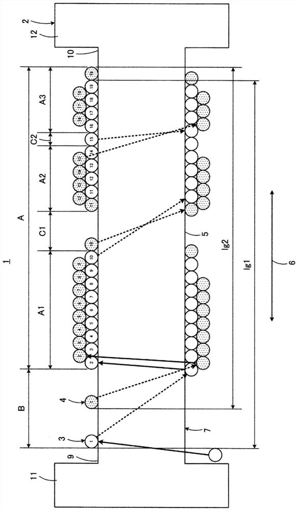
[0100] In the second embodiment, as Figure 8 As shown, the first conductive wire 3 and the second conductive wire 4 wind around the peripheral surface 5 of the core part 7, from the first end part 9 on the first flange part 11 side to the second end pa...
no. 3 approach
[0124] Figure 11 is a diagram for explaining a common mode choke coil 1b according to a third embodiment of the present invention, and figure 2 or Figure 8 correspond. exist Figure 11 in, right with figure 2 or Figure 8 Components corresponding to the shown components are denoted by the same reference numerals, and overlapping explanations are omitted.
[0125] In the second embodiment, in the switching part C, gaps are provided between the respective turns of the conducting wires 3 and 4 before and after the intersection of the first conducting wire 3 and the second conducting wire 4, but in the third embodiment, there are In the switch part C, no gap is provided between the respective turns of the conducting wires 3 and 4 before and after the intersection of the first conducting wire 3 and the second conducting wire 4 . Other points in the third embodiment are the same as those in the second embodiment.
PUM
 Abstract
Description
Claims
Application Information
 - R&D Engineer
- R&D Manager
- IP Professional
- Industry Leading Data Capabilities
- Powerful AI technology
- Patent DNA Extraction
Browse by: Latest US Patents, China's latest patents, Technical Efficacy Thesaurus, Application Domain, Technology Topic, Popular Technical Reports.
© 2024 PatSnap. All rights reserved.Legal|Privacy policy|Modern Slavery Act Transparency Statement|Sitemap|About US| Contact US: help@patsnap.com