
Optical remote sensing image thick cloud removal method based on virtual image construction

An optical remote sensing and virtual image technology, applied in image enhancement, image data processing, image memory management, etc., can solve the problem that optical remote sensing images cannot obtain surface information, and achieve the effect of improving application ability and overcoming accuracy differences.

Active Publication Date: 2022-04-08
CAPITAL NORMAL UNIVERSITY
View PDF7 Cites 0 Cited by
  • Summary
  • Abstract
  • Description
  • Claims
  • Application Information

AI Technical Summary

Problems solved by technology

[0007] The problem that the surface information cannot be obtained from the optical remote sensing image under the condition of cloud pollution

Method used


Image

  • Optical remote sensing image thick cloud removal method based on virtual image construction
  • Optical remote sensing image thick cloud removal method based on virtual image construction
  • Optical remote sensing image thick cloud removal method based on virtual image construction

Examples


Embodiment 1

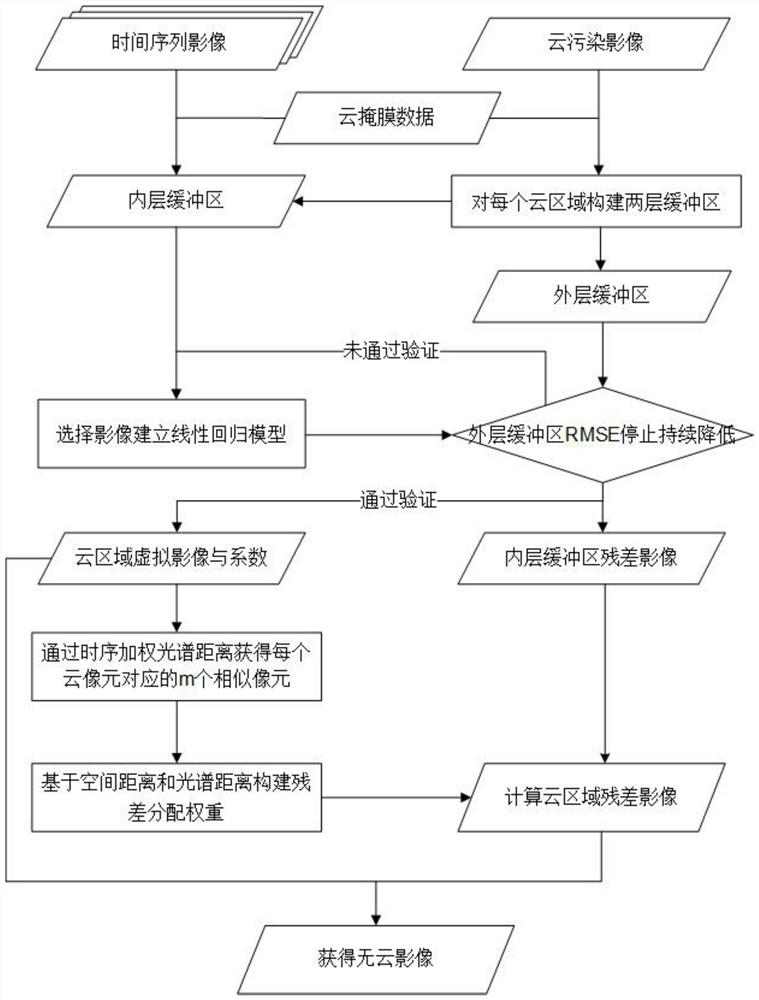
[0060] see figure 1 , the present invention proposes a method for removing thick clouds from optical remote sensing images based on building a virtual image, and the specific method steps are as follows:

[0061] S1. Obtain the time series Landsat surface reflectance product images of the target research area for data preparation;

[0062] S2. Mask the time series Landsat remote sensing image through the quality detection band contained in the data. When the quality detection band data identifies the pixel as a cloud or cloud shadow, set the pixel value to a null value, that is, The part that performs cloud removal;

[0063] S3. Select the cloud pollution image to be processed, and build an inner buffer and an outer buffer for each cloud area. Through the principle of the expansion algorithm, taking the construction of the inner buffer as an example, by using the sliding window, when the window memory When there are cloud pixels, all the pixels (except cloud pixels) in this ...

Embodiment 2

[0092] see Figure 2-3 , the difference between this implementation mode and the specific implementation mode one is:

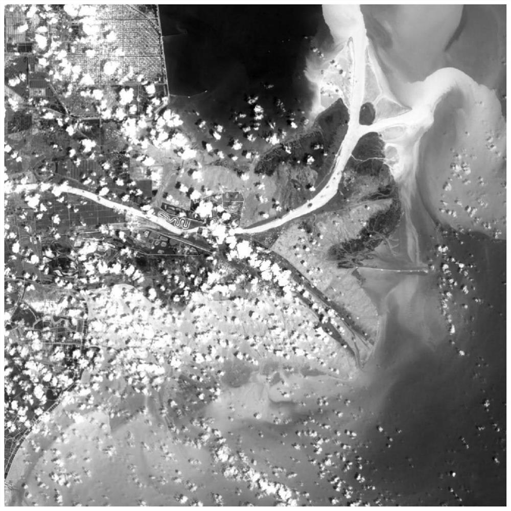
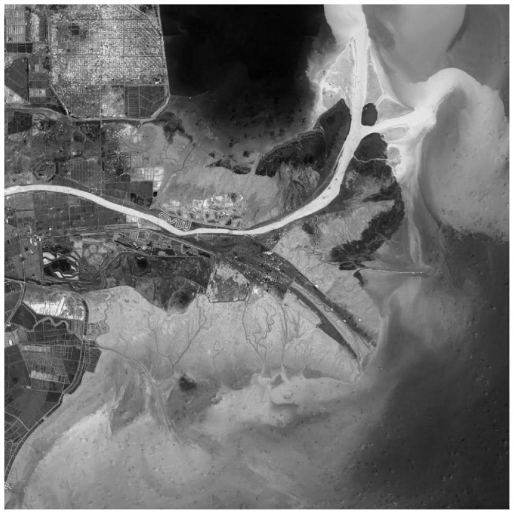
[0093] This implementation case selects the Yellow River Delta as the research area. This method mainly performs code writing and calculation on the MATLAB software, and the feasibility of the present invention is further supplemented and proved by applying the method proposed by the present invention to an actual case below.

[0094] Step 1. Obtain the Landsat 8 satellite surface reflectance products covering the Yellow River Delta region in 2019.

[0095] Step 2: Through the quality detection band in the Landsat 8 data, obtain the cloud and its shadow distribution area corresponding to each image, use ENVI software to perform mask processing, and set the cloud area to a null value.

[0096] Step 3. Select the Landsat 8 image on July 18, 2019 ( figure 2), process the data as the target, write the code on the MATLAB software, firstly extract each cloud re...


PUM


Abstract

The invention discloses an optical satellite remote sensing image thick cloud removal method based on a virtual image. Firstly, for an image covered by thick cloud, cloud pixels are removed by using cloud mask data, the removed cloud pixels are used as target pixels to be recovered, and connected target pixels are used as cloud areas to be recovered. And performing cloud removal processing on each cloud region in the image. Then, constructing a time sequence weighted spectral distance, and searching for similar pixels in an inner buffer area for each target pixel; and calculating the weight by using the time sequence weighted spectral distance and the spatial distance of the similar pixels and the target pixels, and distributing the residual error of the similar pixels to the target pixels through a weight linear distribution method to obtain the residual error of the target pixels so as to obtain the residual error image of the cloud region. And finally, combining the virtual image and the residual image of the cloud region to obtain a cloudless image of the cloud region. The problem that the surface information of the optical remote sensing image cannot be obtained under the condition of cloud pollution is effectively solved.

Description

technical field [0001] The invention belongs to the field of image processing of remote sensing images, and in particular relates to a method for removing thick clouds of optical remote sensing images based on constructing virtual images. Background technique [0002] As an important data source for large-scale and long-term earth observation, satellite remote sensing plays an irreplaceable role in land use change, crop management, and environmental monitoring. However, during the application of satellite data, optical satellites will inevitably be affected by cloud pollution, resulting in greatly reduced data availability. Whether it is for long-term monitoring of ground phenology, or for short-term sudden disasters, thick cloud cover brings challenges to the timeliness and accuracy of monitoring. Therefore, the reconstruction of missing values ​​caused by thick clouds is very important for the application of satellite data. [0003] In the thick cloud removal methods pro...

Claims


Application Information

Patent Timeline
Patent Type & Authority Applications(China)
IPC IPC(8): G06T5/00G06T5/30G06T1/60
Inventor 柯樱海王展鹏吕明苑朱丽娟
Owner CAPITAL NORMAL UNIVERSITY
Learn More