
Heat pump unit defrosting control method and heat pump unit

A technology of heat pump unit and control method, which is applied in the direction of space heating and ventilation control input, heating mode, heating and ventilation control system, etc., and can solve the problems of easy damage or failure of the water flow switch, air intake, freezing and cracking of components, etc., to achieve Avoid easy triggering of false protection, avoid high failure rate, and improve accuracy

Active Publication Date: 2022-04-08
ZHONGSHAN AMITIME ELECTRIC CO LTD
View PDF11 Cites 1 Cited by
  • Summary
  • Abstract
  • Description
  • Claims
  • Application Information

AI Technical Summary

Problems solved by technology

[0003] However, the water flow switch has the following defects: when the heat pump air conditioner is installed, if the flow gear of the circulating water pump does not meet the flow requirements of the unit, it is easy to cause the water flow of the unit to be lower than the cut-off value of the water flow switch, triggering the false protection action of the unit, Reduce the reliability of the unit operation; at the same time, the circulating water pump works abnormally, the water pipeline leaks or air enters, the water flow switch is easily damaged or fails, etc., all of which will cause the heat pump air conditioner to stop running
When defrosting is performed under outdoor low temperature conditions, the heat pump unit stops running due to lack of water flow, and its refrigerant pipelines, water pipelines and other components are easily frozen due to the low temperature, causing pipelines to freeze or components to freeze, causing the entire unit to damaged equipment

Method used


Image

  • Heat pump unit defrosting control method and heat pump unit
  • Heat pump unit defrosting control method and heat pump unit

Examples


Embodiment Construction

[0025] In order to make the purpose, technical solution and advantages of the present application clearer, the embodiments of the present application will be further described in detail below in conjunction with the accompanying drawings.

[0026] It should be clear that the described embodiments are only some of the embodiments of the present application, rather than all of the embodiments. Based on the embodiments in the embodiments of the present application, all other embodiments obtained by persons of ordinary skill in the art without making creative efforts belong to the protection scope of the embodiments of the present application.

[0027] The terms used in the embodiments of the present application are only for the purpose of describing specific embodiments, and are not intended to limit the embodiments of the present application. The singular forms "a", "said" and "the" used in the embodiments of this application and the appended claims are also intended to include ...


PUM


Abstract

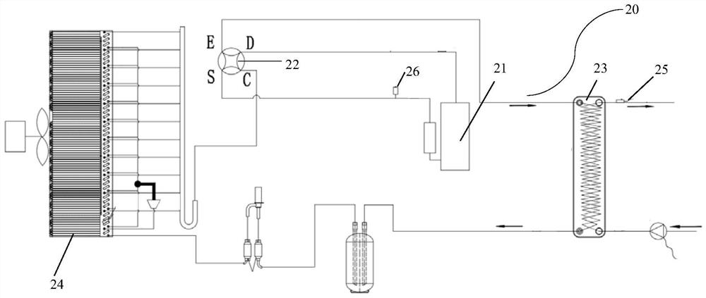
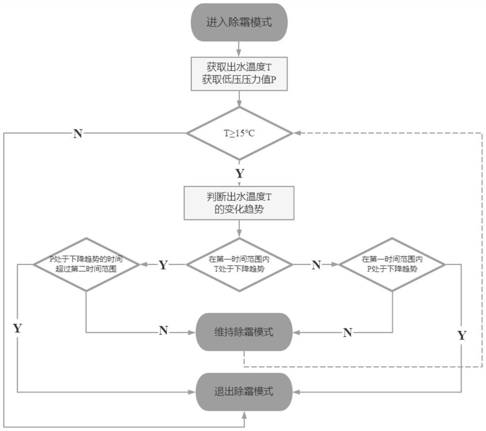
The invention relates to a control method for preventing failure caused by water flow loss during defrosting of a heat pump unit. The heat pump unit comprises a shell, a compressor, a four-way valve, a water side heat exchanger, an air side heat exchanger, a water outlet temperature sensor, a low-pressure pressure sensor and a refrigerant pipeline, wherein the compressor, the four-way valve, the water side heat exchanger and the air side heat exchanger are arranged in the shell, and the refrigerant pipeline communicates with the compressor, the four-way valve, the water side heat exchanger and the air side heat exchanger. The water outlet temperature sensor is arranged at the water drainage end of the water side heat exchanger. The low-pressure pressure sensor is arranged at the air return end of the compressor. The method comprises the following steps that after a defrosting mode is started, the outlet water temperature is obtained through the outlet water temperature sensor, and the low-pressure value is obtained through the low-pressure sensor; and if the outlet water temperature is larger than or equal to the preset temperature threshold value, and within the set first time range, the outlet water temperature is not in the decreasing trend, and the low-pressure value is in the decreasing trend, the defrosting mode is quitted. According to the method, the running reliability of the unit is enhanced, and the safety of the unit during defrosting is improved.

Description

technical field [0001] The invention relates to the technical field of heat pump air conditioners, in particular to a defrosting control method for a heat pump unit and the heat pump unit. Background technique [0002] With the development of heat pump air conditioner technology and the enhancement of people's awareness of energy conservation and environmental protection, more and more heat pump air conditioners adopt water flow switches. The water flow switch is used to detect the water flow in the heat pump air conditioner. When it detects that the water flow is lower than the set cut-off value, the water flow switch will send a cut-off signal to the heat pump air conditioner, and the heat pump air conditioner will stop running to prevent the heat pump air conditioner from being in the water. Running under the condition of insufficient flow will damage the unit. [0003] However, the water flow switch has the following defects: when the heat pump air conditioner is instal...

Claims


Application Information

Patent Timeline
Patent Type & Authority Applications(China)
IPC IPC(8): F24F11/41F24F11/64F24F11/61F24F140/20F24F140/10
CPCY02B30/70
Inventor 黄志威林建邦童风喜
Owner ZHONGSHAN AMITIME ELECTRIC CO LTD
Learn More