Equipment and method for treating hypoxia of return air corner

A corner and equipment technology, which is applied in the field of equipment for treating low oxygen in the return air corner, can solve the problems of low oxygen concentration, can not completely solve the problem of low oxygen in the return air corner, and reduced oxygen concentration in the return air corner of the working face.

Pending Publication Date: 2022-04-08
XUZHOU MINING BUSINESS GROUP +3
View PDF8 Cites 0 Cited by
  • Summary
  • Abstract
  • Description
  • Claims
  • Application Information

AI Technical Summary

Problems solved by technology

[0002] With the continuous deepening of coal mining depth and the continuous increase of mining intensity, the oxygen concentration is often lower than the safe value, and the concentration of toxic and harmful gases exceeds the standard in the return air corner during the recovery of the fully mechanized top coal caving face. Bring major safety hazards, even stop production and take measures to prevent and control, seriously restricting coal mine production efficiency
The main reason is that the hypoxic gas in the goaf gushes out from the return air corner at the lowest negative pressure point of the fully mechanized mining face, resulting in a decrease in the oxygen concentration in the return air corner of the working face
[0003] At present, the commonly used methods for the prevention and control of hypoxia in the working face mainly include equalizing pressure, plugging the upper and lower wells, building windshield walls at the upper and lower corners, setting up wind guide curtains at the upper corners, hanging windshield curtains at the upper and lower corners, and installing special Exhaust fans, etc., but their devices are relatively complicated, and the main control ideas are mostly to reduce the air leakage from the goaf to the working face, which cannot completely solve the problem of low oxygen in the return air corner

Method used


Image

  • Equipment and method for treating hypoxia of return air corner
  • Equipment and method for treating hypoxia of return air corner
  • Equipment and method for treating hypoxia of return air corner

Examples


Embodiment Construction

[0021] Embodiments of the present invention are described below through specific examples, and those skilled in the art can easily understand other advantages and effects of the present invention from the content disclosed in this specification. The present invention can also be implemented or applied through other different specific implementation modes, and various modifications or changes can be made to the details in this specification based on different viewpoints and applications without departing from the spirit of the present invention. It should be noted that the diagrams provided in the following embodiments are only schematically illustrating the basic concept of the present invention, and the following embodiments and the features in the embodiments can be combined with each other in the case of no conflict.

[0022] Wherein, the accompanying drawings are for illustrative purposes only, and represent only schematic diagrams, rather than physical drawings, and should...


PUM


Abstract

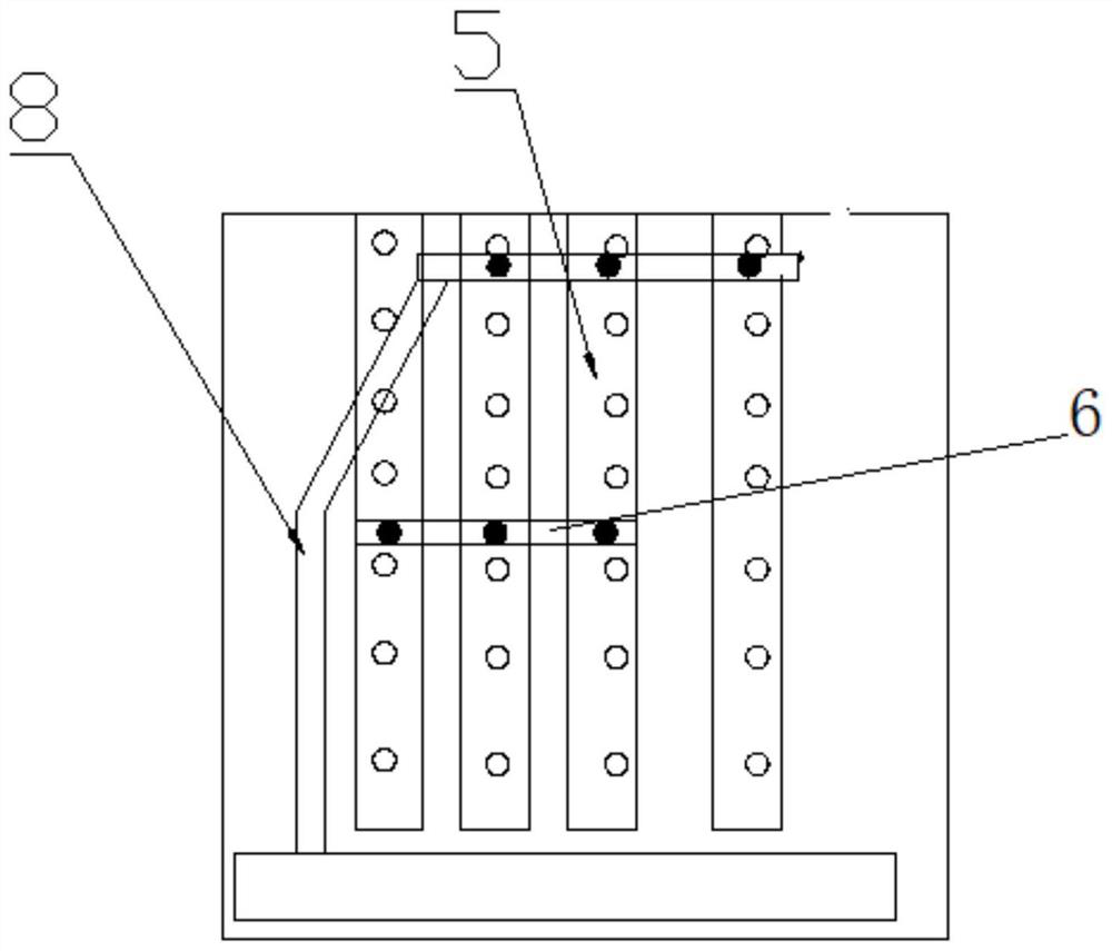
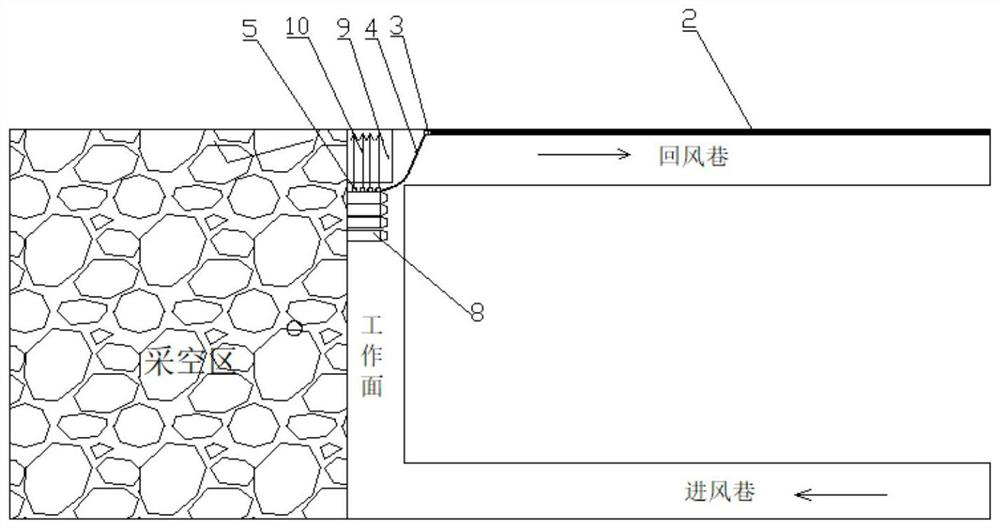
The invention relates to equipment and a method for treating hypoxia of a return air corner, and belongs to the technical field of coal mine safety. The equipment comprises an air compressor located on the ground and a compressed air pipeline connected with the air compressor, a connecting device is arranged at the end, away from the air compressor, of the compressed air pipeline, the connecting device is communicated with an air outlet device through a high-pressure connecting pipe, the air outlet device comprises a plurality of hollow vertical pipes, the two ends of each vertical pipe are sealed, and each vertical pipe is provided with an air inlet connected with the high-pressure connecting pipe. A plurality of uniformly arranged air outlet holes are formed in the vertical pipe in the axial extension direction; the vertical pipe is vertically fixed to a hydraulic support at the air return corner of the working face, so that the air outlet directly faces the air return corner. A compressed air belt is formed through the equipment, and the technical problem of low oxygen of the air return corner is solved.

Description

technical field [0001] The invention belongs to the technical field of coal mine safety, and in particular relates to a device and a method for controlling low oxygen in return air corners. Background technique [0002] With the continuous deepening of coal mining depth and the continuous increase of mining intensity, the oxygen concentration is often lower than the safe value and the concentration of toxic and harmful gases exceeds the standard in the return air corner during the recovery of the fully mechanized top coal caving face. Bring major safety hazards, and even stop production to take measures to prevent and control, seriously restricting the production efficiency of coal mines. The main reason is that the hypoxic gas in the goaf rushes out from the return air corner at the lowest negative pressure point of the fully mechanized mining face, resulting in a decrease in the oxygen concentration in the return air corner of the working face. [0003] At present, the co...

Claims


Application Information

Patent Timeline
Patent Type & Authority Applications(China)
IPC IPC(8): E21F1/00E21D23/04E21F5/04
Inventor 王克军陈辉李剑锋刘国忠项宗文李尚国位玉红徐俊刘金虎王正辉田素超闫凯王振国杜云峰魏丕军焦彦锦崔向兴宋铁柱买买提沙依提·依坎白尔迪李明华康
Owner XUZHOU MINING BUSINESS GROUP
Why Eureka
Try Eureka