
Patsnap Eureka
For R&D, Patsnap Eureka makes reading and utilizing patents & technical documents easy.
Patsnap Eureka AIR
Designed for self-driven R&D workflows. Generate viable solutions, solve complex R&D challenges, empower your innovation with AI.

Patsnap Eureka Materials
Designed for material experts only. Revolutionize your material R&D, from search, analyze, to developing new materials.

TechResearch
Generate reliable direction feasibility study reports for your R&D in just a few steps.

TechSeek
Discover and master advanced knowledge NOW. Basics, ideas, possibilities, all at once.

TechMind
As an expert in R&D Theories, TechMind can generates customized viable solutions instantly.

TechRisk
Analyze your overall solution with one click, know your potential R&D risks in advance.

TechMonitor
Get weekly tech updates, stay abreast of the latest tech innovations and key insights.
Circuit board film tearing device
A circuit board and film device technology, applied in the directions of printed circuit, printed circuit manufacturing, packaging, etc., can solve the problems of circuit board damage, inconvenient circuit board automatic tearing film, inconvenient energy-saving operation, etc., to reduce energy consumption and facilitate Clamping, time-saving effect
- Summary
- Abstract
- Description
- Claims
- Application Information
AI Technical Summary
Problems solved by technology
Method used
Image

Examples
Embodiment 1
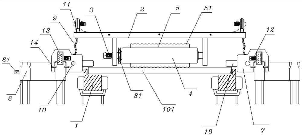
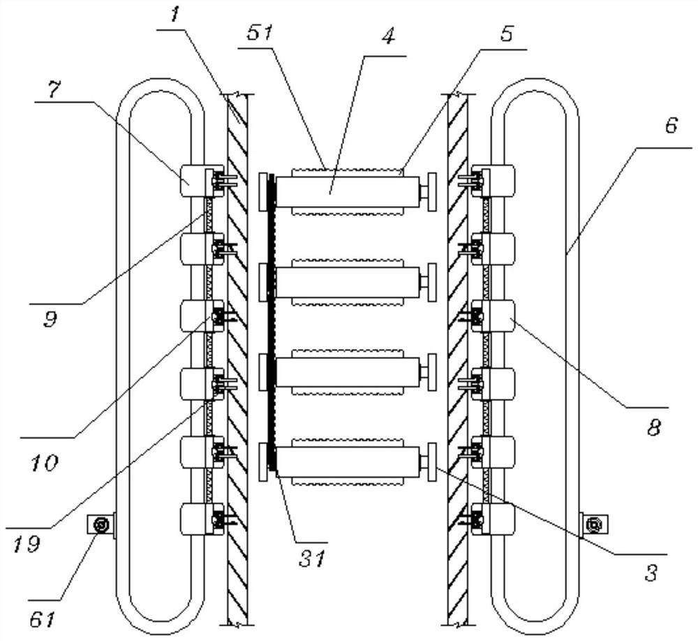
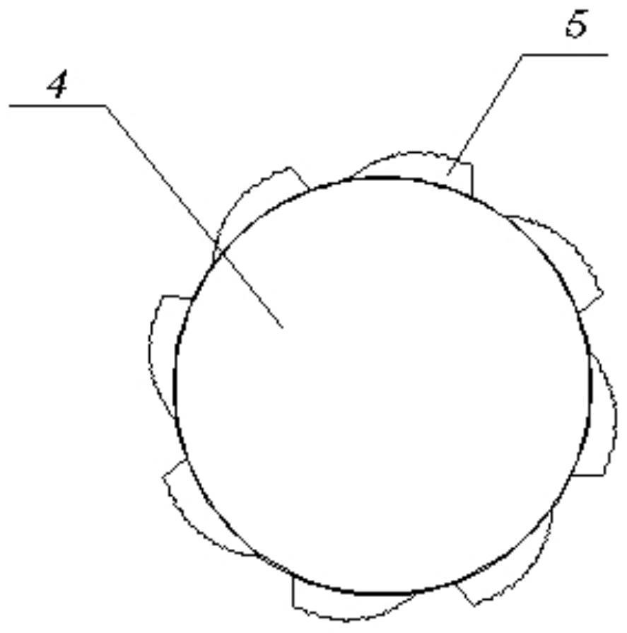
[0029] see Figure 1-4, including a transmission belt 1, the transmission belt 1 is distributed on both sides in a strip-shaped convex structure, and a circuit board 101 is placed on the transmission belt 1, and the two ends of the transmission belt 1 are provided with mounting brackets 2; it also includes: the first Motor 3, the first motor 3 is fixed on the side of the mounting frame 2, and the output end of the first motor 3 is connected with a tearing film roller 4, and the tearing film rollers 4 are connected by a chain 31, and the tearing film roller 4 Tear film strips 5 are fixed on the outer side, and the tear film strips 5 are equiangularly distributed on the tear film rollers 4, and the tear film strips 5 are designed in an arc-shaped convex structure, and the tear film rollers 4 are equidistantly distributed on the bottom of the mounting frame 2, Moreover, the height of the tearing film roller 4 increases successively along the transmission direction of the conveyor...
Embodiment 2
[0031] see Figure 1-2 and Figure 5 , the guide rail 6, the guide rail 6 is fixed on the ground, and the guide rail 6 is located on both sides of the conveyor belt 1, and the guide rail 6 is provided with a laminated vehicle head 7 and a laminated film vehicle body 8, and an infrared sensor 61 is fixed on the outside of the guide rail 6 A connecting hose 9 is provided between the clamped headstock 7 and the clamped vehicle body 8, and a pressure passage 10 is provided in the clamped headstock 7 and the laminated vehicle body 8, and the pressure passage 10 and the connecting hose 9 are connected to each other. The top of hose 9 runs through and is connected to the output end of air pump 11, and air pump 11 is fixed on the top edge place of mounting frame 2, and the second motor 12 is embedded in the clamping headstock 7, and the output of second motor 12 The end is connected with traveling roller 13, and both sides of the inner wall of the laminated vehicle head 7 and the lam...
PUM
 Abstract
Description
Claims
Application Information
 - R&D Engineer
- R&D Manager
- IP Professional
- Industry Leading Data Capabilities
- Powerful AI technology
- Patent DNA Extraction
Browse by: Latest US Patents, China's latest patents, Technical Efficacy Thesaurus, Application Domain, Technology Topic, Popular Technical Reports.
© 2024 PatSnap. All rights reserved.Legal|Privacy policy|Modern Slavery Act Transparency Statement|Sitemap|About US| Contact US: help@patsnap.com