
Floating positioning device for underwater equipment

A technology of positioning device and underwater equipment, which is applied in the directions of underwater operation equipment, lighting device, lighting and heating equipment, etc. The effect of increasing the difficulty of recycling, convenient and rapid positioning, and high recognition

Active Publication Date: 2022-04-08
HANGZHOU DIANZI UNIV
View PDF8 Cites 2 Cited by
  • Summary
  • Abstract
  • Description
  • Claims
  • Application Information

AI Technical Summary

Problems solved by technology

[0003]Currently, the corresponding underwater equipment is deployed to the target area through the hull and underwater equipment deployment recovery device, and in order to facilitate the recovery of underwater equipment, it is usually necessary to install The floating positioning device ensures the stability of the detection depth of underwater equipment, and at the same time facilitates rapid recovery in the later stage. However, the waves in the ocean are relatively large, and the positioning signal is not good. Most of the existing floating positioning devices rely on the Beidou satellite positioning system for positioning and recovery. , when there is a problem with the positioning system, it is difficult to find the underwater detection equipment, which affects the progress of recovery. Therefore, we propose a floating positioning device for underwater equipment to solve the above problems

Method used


Image

  • Floating positioning device for underwater equipment
  • Floating positioning device for underwater equipment
  • Floating positioning device for underwater equipment

Examples


Embodiment 1

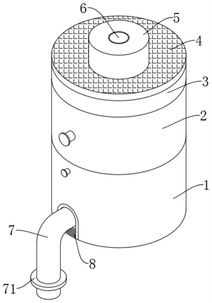
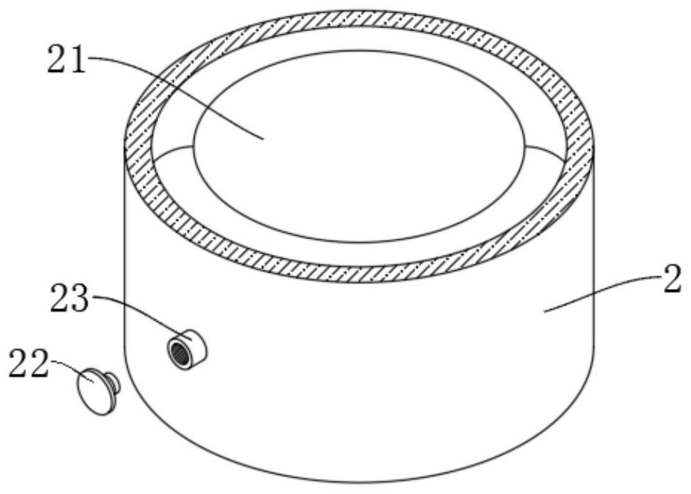
[0023] refer to figure 1 , 5 , which is the first embodiment of the present invention, this embodiment provides a floating positioning device for underwater equipment, including a connecting cylinder 1, the top end of the connecting cylinder 1 is coaxially fixedly connected with an airbag housing 2, and the airbag The top of the shell 2 is coaxially fixedly connected with a protective shell 3, and the inner wall of one side of the protective shell 3 is fixedly connected with a lithium battery 9, and one side of the lithium battery 9 is provided with a mechanical timer 10, and the top edge of the protective shell 3 The solar panel 4 is fixedly connected, the center of the solar panel 4 is fixedly connected with the indicator light 5, and the center of the indicator light 5 is fixedly connected with the signal component 6;

[0024] A winding assembly 13 is installed rotatably in the connecting cylinder 1, and a connecting rope 7 is fixedly connected to the winding assembly 13. ...

Embodiment 2

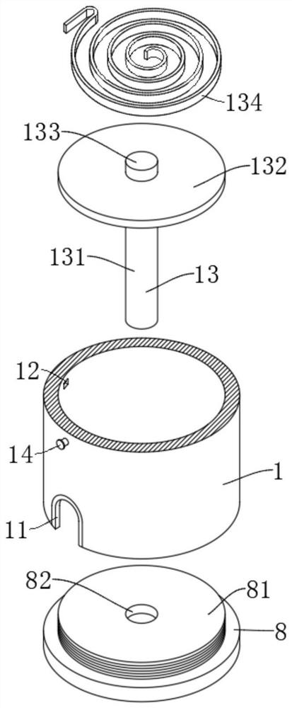
[0026] refer to Figure 1-5 , is the second embodiment of the present invention. This embodiment is based on the previous embodiment. Specifically, one end of the end cover 8 is provided with a toggle groove, and the other end is fixedly connected with a threaded column 81, and the center of the threaded column 81 is recessed. There is an embedded hole 82, and the winding assembly 13 includes a winding roller 131. One end of the winding roller 131 is rotatably connected to the insertion hole 82, and the other end is connected to a turntable 132 through a threaded structure. The winding roller 131 connected by the threaded structure is convenient for winding. The roller 131 is disassembled to facilitate the replacement of the connecting rope 7 of different length materials, which increases the applicability of the present invention. The center of the side of the rotating disk 132 away from the winding roller 131 is fixedly connected with a connecting shaft 133, and one end of th...

Embodiment 3

[0032] refer to Figure 1-5 , which is the third embodiment of the present invention. This embodiment is based on the above two embodiments. When in use, the connecting rope 7 is pulled out and fixedly connected to the underwater equipment, and the stop ring 71 fixedly connected on the connecting rope 7 is convenient for pulling out The connecting rope 7 prevents the connecting rope 7 from protruding into the connecting cylinder 1 and cannot be taken out. At the same time, the end cover 8 is connected to the connecting cylinder 1 through a threaded structure, which is convenient for disassembly and replacement of the length and material of the connecting rope 7. Deeply pull out the connecting rope 7 of the corresponding length, tighten the locking pin 14, snap into the side wall of the turntable 132, and then lock the turntable 132 to ensure that the length of the connecting rope 7 is fixed, and inflate the airbag 21 through the inflation port 23, Ensure that the present inven...


PUM


Abstract

The invention discloses a floating positioning device for underwater equipment, which comprises a connecting cylinder, an air bag shell is coaxially and fixedly connected to the top end of the connecting cylinder, a protective shell is coaxially and fixedly connected to the top end of the air bag shell, a lithium battery is fixedly connected to the inner wall of one side of the protective shell, and a mechanical timer is arranged on one side of the lithium battery. The top edge of the protective shell is fixedly connected with a solar panel, the center of the solar panel is fixedly connected with an indicator light, and the center of the indicator light is fixedly connected with a signal assembly; a winding assembly is rotationally installed in the connecting cylinder, a connecting rope is fixedly connected to the winding assembly, and the bottom end of the connecting cylinder is connected with an end cover through a threaded structure. The connecting rope is fixedly connected with the underwater equipment, the locking pin is matched to fix the connecting rope, so that the submerging depth of the underwater equipment is kept unchanged, the air bag is filled with air, and it is guaranteed that the device floats on the sea surface.

Description

technical field [0001] The invention relates to the technical field of underwater equipment positioning, in particular to a floating positioning device for underwater equipment. Background technique [0002] With the increasing demand for marine exploration and environmental monitoring, underwater detection equipment has become the main force to perform these tasks. For example, sonar is an electronic device that uses the propagation characteristics of sound waves underwater to complete underwater detection and communication tasks through electro-acoustic conversion and information processing. It is the most widely used and most important device in underwater acoustics. [0003] At present, the corresponding underwater equipment is deployed to the target area through the deployment and recovery device of the hull and underwater equipment. It is also convenient for quick recovery in the later stage, but the waves in the ocean are relatively large, and the positioning signal ...

Claims


Application Information

Patent Timeline
Patent Type & Authority Applications(China)
IPC IPC(8): B63B22/00B63C11/52F21S9/03
Inventor 方远陈升方妍姚道震张林芝郑佳胤
Owner HANGZHOU DIANZI UNIV
Learn More