
Chemical process pump with heat dissipation and shock absorption functions and method

A technology of process pumps and chemical industry, applied in springs/shock absorbers, components of pumping devices for elastic fluids, pumps, etc., can solve problems affecting heat dissipation rate, heat cannot be released quickly, etc., to avoid accumulation, Increased speed, the effect of ensuring stable operation

Pending Publication Date: 2022-04-05
鲲玖泵业(无锡)有限公司
View PDF8 Cites 1 Cited by
  • Summary
  • Abstract
  • Description
  • Claims
  • Application Information

AI Technical Summary

Problems solved by technology

[0006] The invention provides a chemical process pump and method with heat dissipation and shock absorption functions, which solves the problem that a large amount of heat will be generated on the surf

Method used


Image

  • Chemical process pump with heat dissipation and shock absorption functions and method
  • Chemical process pump with heat dissipation and shock absorption functions and method
  • Chemical process pump with heat dissipation and shock absorption functions and method

Examples


no. 1 example

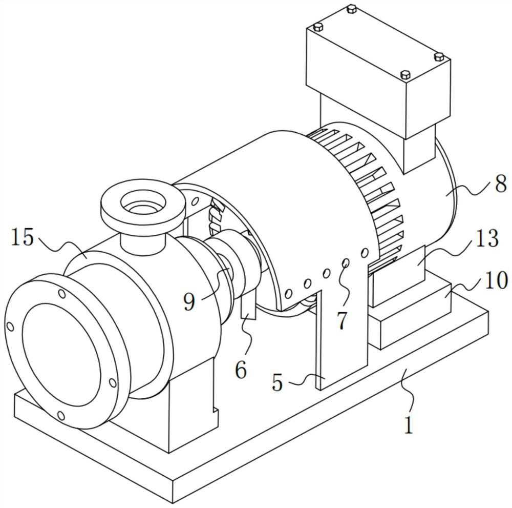
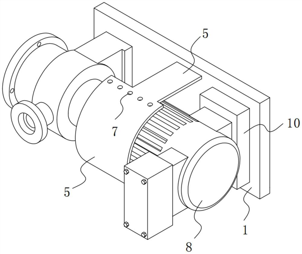
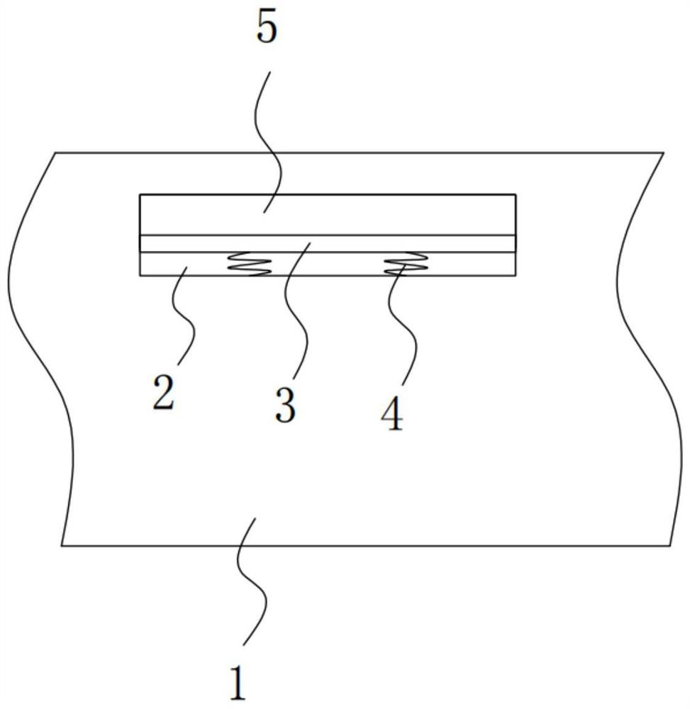
[0035] Please refer to figure 1 , figure 2 , image 3 , Figure 4 with Figure 5 ,in, figure 1 Schematic diagram of the structure of the first embodiment of the chemical process pump and method provided by the present invention with the function of heat dissipation and shock absorption; figure 2 for figure 1 Schematic diagram of the side view structure of the motor shown; image 3 for figure 1 A schematic cutaway view of the base shown; Figure 4 for figure 1 The schematic cross-sectional view of the box shown; Figure 5 for Figure 4 The partial enlarged schematic diagram at A is shown. A chemical process pump and method with heat dissipation and shock absorption functions, including:

[0036] base1;

[0037] The installation groove 2, the installation groove 2 is opened in the inside of the base 1, and a clamping plate 3 is slidably connected between the two sides inside the installation groove 2, and a limit spring is arranged on one side of the clamping plat...

no. 2 example

[0065] Please refer to Image 6 , Based on the chemical process pump and method with heat dissipation and shock absorption function provided in the first embodiment of the present application, the second embodiment of the present application proposes another chemical process pump and method with heat dissipation and shock absorption function. The second embodiment is only a preferred mode of the first embodiment, and the implementation of the second embodiment will not affect the independent implementation of the first embodiment.

[0066] Specifically, the difference between the chemical process pump and the method provided by the second embodiment of the present application is that: the bottom of the base 1 is fixedly connected with a bottom box 20, and the two inside the bottom box 20 A moving plate 21 is slidably connected between the sides, and the bottom of the moving plate 21 is provided with a moving wheel 22 , and the bottom of the moving wheel 22 passes through the b...


PUM


Abstract

The invention provides a chemical process pump with heat dissipation and shock absorption functions and a method. The mounting groove is formed in the base, a clamping plate is slidably connected between the two sides of the interior of the mounting groove, a limiting spring is arranged on one side of each clamping plate, and one end of each limiting spring is arranged on one side of the interior of the mounting groove; and the protective cover is arranged in the mounting groove. According to the chemical process pump with the heat dissipation and shock absorption functions and the method, the fan blades are arranged on the rotating shaft, the motor drives the fan blades to rotate along with the rotating shaft in the starting process, heat generated at the rotating shaft is blown, heat release is accelerated, heat is prevented from being locally accumulated, normal heat dissipation is not affected, and the service life of the fan blades is prolonged. And heat dissipation holes are formed in the side edge of the protective cover, so that part of heat can flow out, the heat release rate is increased, and it is ensured that the chemical process pump can stably operate.

Description

technical field [0001] The invention relates to the technical field of chemical process pumps, in particular to a chemical process pump with heat dissipation and shock absorption functions and a method thereof. Background technique [0002] Chemical process pump is the general name of various pumps in the chemical production process. The pump is equipped with large power, high speed, small overall volume, simple structure, and easy maintenance. However, it is high in temperature, easy to wear, and has a large maintenance coefficient. It is suitable for conveying neutral or Corrosive, clean or liquid media containing solid particles, low temperature or high temperature, most of the existing chemical process pumps are small and medium pump bodies suitable for individual enterprises or private enterprises. [0003] When the chemical process pump is used, the external pipeline is connected to the discharge port to transport chemical materials to meet the needs of use. [0004] ...

Claims


Application Information

Patent Timeline
IPC IPC(8): H02K5/24H02K9/06H02K5/20F04D13/06F04D29/68F16F15/067
Inventor 皱睿
Owner 鲲玖泵业(无锡)有限公司
Learn More