
Middle support bracket system of bridge girder erection machine

A technology of a bracket system and a bridge erection machine, which is applied in the field of the middle bracket bracket system, can solve the problems of cumbersome operation, heavy workload, complex terrain, etc., and achieves the effect of safe and reliable operation and stable longitudinal movement.

Pending Publication Date: 2022-04-05
ROAD & BRIDGE INT +1
View PDF6 Cites 0 Cited by
  • Summary
  • Abstract
  • Description
  • Claims
  • Application Information

AI Technical Summary

Problems solved by technology

[0003] The high-speed railway passenger dedicated line passes through mostly mountains and rivers, with complex terrain, and there are many bridge-tunnel connecting sections, and the traveling angle of the bridge erecting machine needs to be changed in order to adapt to the complex terrain between the connected sections, but now bridge erection Changing the angle of the machine requires manual disassembly, heavy workload and cumbersome operation

Method used


Image

  • Middle support bracket system of bridge girder erection machine
  • Middle support bracket system of bridge girder erection machine
  • Middle support bracket system of bridge girder erection machine

Examples


Embodiment Construction

[0034] Embodiments of the present application are described in detail below, examples of which are shown in the drawings, wherein the same or similar reference numerals denote the same or similar elements or elements having the same or similar functions throughout. The embodiments described below by referring to the figures are exemplary only for explaining the present application, and are not construed as limiting the present application.

[0035] Aiming at the problems that the existing bridge erecting machine is difficult to construct due to terrain restrictions, and the large steel plate composite girder cannot be erected smoothly, please refer to Figures 1 to 9d , the present application provides a bridge erecting machine 1000 and a bridge erecting method using the bridge erecting machine 1000, which does not require support, high pier gantry, and large-scale lifting equipment, and does not need to level and harden the bridge along the line, and has high construction effi...


PUM


Abstract

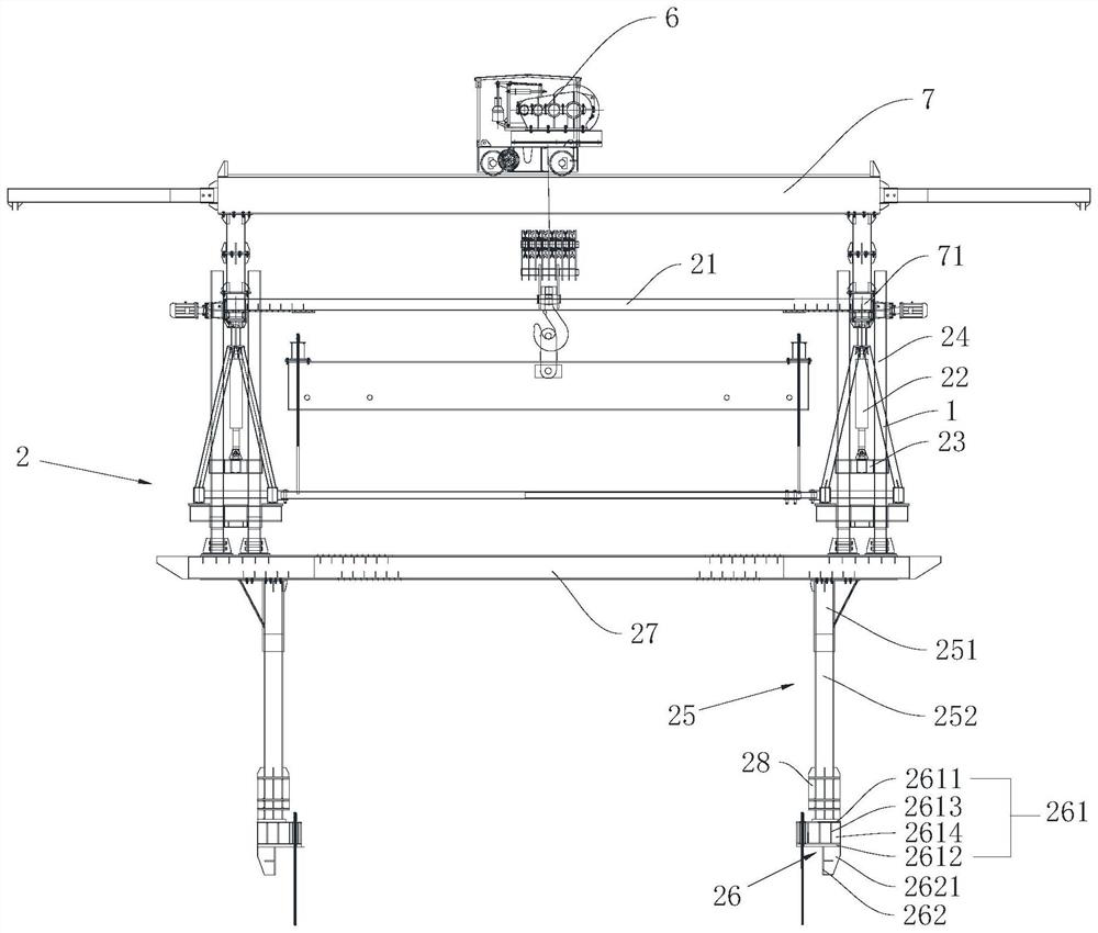
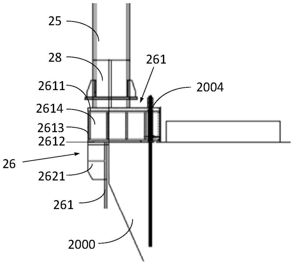
The invention provides a middle support bracket system of a bridge girder erection machine, which is mounted in the middle of the bridge girder erection machine and comprises a middle support leg joist, a main beam longitudinal movement driving mechanism and a transverse walking mechanism, and the main beam longitudinal movement driving mechanism and the transverse walking mechanism are respectively arranged on the upper side and the lower side of the middle support leg joist. The girder longitudinal movement driving mechanism is arranged at the bottom of the girder of the bridge girder erection machine and used for driving the girder to move longitudinally, and the transverse walking wheel box is connected with the middle supporting leg joist and can be used for driving the middle supporting leg joist to move in the transverse bridge direction. The middle of the main beam moves in the transverse bridge direction through the transverse walking mechanism, and the purpose of adjusting the transverse position of the main beam can be achieved. In addition, the position of the front end of the main beam can be limited, the main beam can rotate around the front end of the main beam, the middle of the main beam is pushed through the transverse walking mechanism so that the main beam can rotate around the front end of the main beam, then the angle of the main beam is adjusted, and the construction requirement of the oblique crossing bridge is met.

Description

technical field [0001] The present application relates to the field of bridge construction, in particular to a center support system of a bridge erecting machine. Background technique [0002] The bridge erecting machine lifts the girders, then transports them to the position and puts them down. It is a bridge construction machine that travels on roads and railway tracks and is used to erect small span girders across the entire span. Its fuselage is huge and exceeds the limit of railway transportation, so it must be disassembled and transported, and then assembled and used after arriving at the construction site. [0003] The high-speed railway passenger dedicated line passes through mostly mountains and rivers with complex terrain, and there are many bridge-tunnel connecting sections, and the traveling angle of the bridge erecting machine needs to be changed between the connected sections to adapt to the complex terrain, but now bridge erection Changing the angle of the ma...

Claims


Application Information

Patent Timeline
Patent Type & Authority Applications(China)
IPC IPC(8): E01D21/00E01D21/06
Inventor 吴健张敬弦孙晓飞石琦谢锦华张培李传威李友清周旭
Owner ROAD & BRIDGE INT
Learn More