Positioning auxiliary device for steel truss hoisting and using method thereof

A positioning aid, steel truss technology, applied in the directions of transportation and packaging, load hanging components, etc., can solve the problems of difficult positioning, prolonged construction period, weight and other problems, to ensure safety and stability, ensure accuracy, Simple to use effects

Pending Publication Date: 2022-04-05
中冶(上海)钢结构科技有限公司
View PDF0 Cites 1 Cited by
  • Summary
  • Abstract
  • Description
  • Claims
  • Application Information

AI Technical Summary

Problems solved by technology

However, in the actual installation process, due to the large span and heavy weight of large trusses, positioning is more difficult, and the truss column feet are large in size and block the line of sight, which makes positioning more difficult, and large trusses are often difficult to rely on due to their large size. Visual observation is used to adjust and avoid obstacles in the hoisting process, which is prone to accidents such as scratches and collisions
[0003] At present, most of the positioning methods used are the method of drawing a "cross" line and then manually visually positioning. The positioning error is large and the adjustment is difficult. The positioning can only be carried out by relying on the construction personnel's operating experience, and the positioning takes a long time and is inefficient.
Once a deviation or dislocation occurs, it cannot be corrected in the later stage, and it will affect all secondary components connected to it in subsequent installations
It greatly prolongs the construction period, reduces the construction quality, and causes certain safety hazards to the later use of the truss

Method used


Image

  • Positioning auxiliary device for steel truss hoisting and using method thereof
  • Positioning auxiliary device for steel truss hoisting and using method thereof
  • Positioning auxiliary device for steel truss hoisting and using method thereof

Examples


Embodiment Construction

[0025] The present invention is further illustrated below by specific examples.

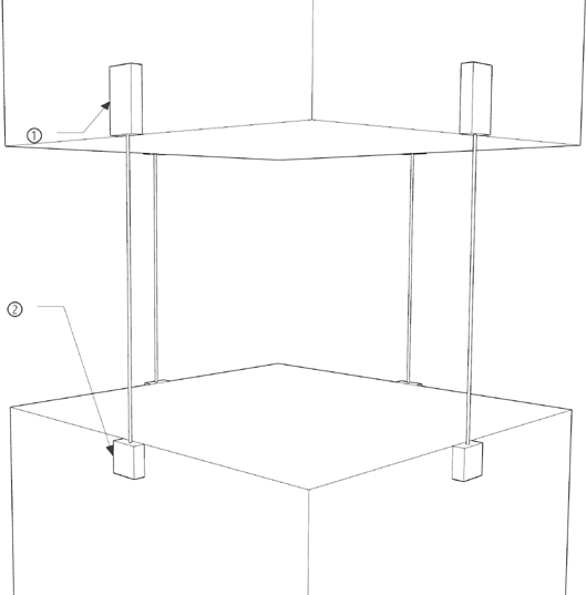
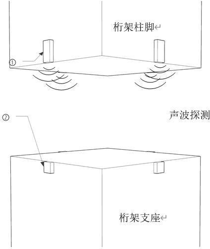
[0026] Such as Figure 1~Figure 5 As shown, a positioning auxiliary device for steel truss hoisting, a sound wave laser compound range finder transmitter (1), a laser range finder receiver (2), a three-dimensional scanner (3) and a computer (4); wherein, the sound wave The laser compound rangefinder transmitting device (1) is installed on the truss column foot, the laser rangefinder receiving device (2) is installed on the truss support, and the three-dimensional scanner (3) and the computer (4) are handheld.

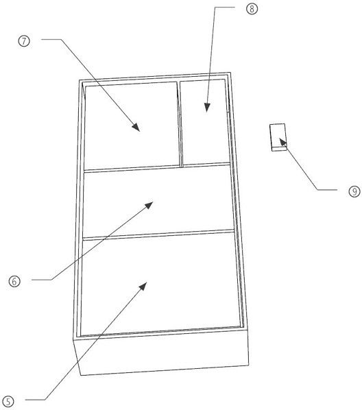
[0027] The positioning auxiliary device for hoisting the steel truss, the acoustic wave laser compound rangefinder launch device (1) has a built-in acoustic wave rangefinder (5), laser rangefinder (5), power supply (7), launch device data signal transmitter (8), transmitting device data signal receiver (9); laser range finder receiving device (2) includes laser range finder receiver (10),...


PUM


Abstract

The invention particularly relates to a positioning auxiliary device for hoisting a steel truss. The device is characterized by comprising an acoustic wave and laser composite range finder transmitting device (1), a laser range finder receiving device (2), a three-dimensional scanner (3) and a computer (4), wherein the sound wave and laser composite range finder transmitting device (1) is installed on a truss column foot, the laser range finder receiving device (2) is installed on a truss support, and the three-dimensional scanner (3) and the computer (4) are used in a handheld mode. In the hoisting process of the large truss, the relative position relation between the truss and surrounding obstacles can be controlled in real time, real-time position detection of the truss and the surrounding obstacles is achieved, even if the column foot of the truss is located in a view blind area, the column foot of the truss can still be prevented from colliding with the surrounding obstacles or rubbing the surrounding obstacles through the method and the actual field operation, and the hoisting safety of the large truss is improved. And the safety and the stability in the hoisting process are ensured.

Description

technical field [0001] The invention relates to the technical field of steel structure installation, in particular to a positioning auxiliary device for steel truss hoisting and a method for using the same. Background technique [0002] In the field of engineering, the hoisting and installation accuracy of large trusses affects the installation accuracy and stability of the entire structure. However, in the actual installation process, due to the large span and heavy weight of large trusses, positioning is more difficult, and the truss column feet are large in size and block the line of sight, which makes positioning more difficult, and large trusses are often difficult to rely on due to their large size. Visual observation is used to adjust and avoid obstacles during the hoisting process, which is prone to accidents such as scratches and collisions. [0003] The current positioning method is mostly the method of drawing a "cross" line and then manually visually positioning...

Claims


Application Information

Patent Timeline
Patent Type & Authority Applications(China)
IPC IPC(8): B66C13/08B66C13/16B66C13/46B66C13/48
Inventor 官翔宇闫保全张开甲陈烨黄辰来周刚张利
Owner 中冶(上海)钢结构科技有限公司
Why Eureka
Try Eureka