Transformer operation monitoring device

A technology for operation monitoring and transformers, applied in the field of transformers, can solve problems such as high temperature faults at the joints, failure to respond in time, burning of weeds and other objects, to avoid wind, rain and sun exposure, and improve monitoring effects , improve the effect of the effect

Active Publication Date: 2022-04-05
江苏天瑞变压器有限公司
View PDF6 Cites 0 Cited by
  • Summary
  • Abstract
  • Description
  • Claims
  • Application Information

AI Technical Summary

Problems solved by technology

[0004]Transformers are widely used, such as power transformers, distribution transformers, dry-type transformers, amorphous alloy transformers, wound core transformers, in rural areas, large-scale power transmission and transformation Transformers are relatively common, and transformers will also have faults when they are in use, such as circuit faults, winding faults, transformer oil leakage faults, joint temperature, high faults, etc. Install monitoring equipment to monitor the operation of the transformer, but the general monitoring equipment has only one monitoring function. When a fire is caused by a short circuit or other reasons, it cannot respond in time, and the formed electric spark will ignite the surrounding objects, mainly in rural areas. If the ground at the bottom of the transformer has not been treated for a long time and has weeds, objects such as weeds will burn, which poses a great safety hazard

Method used


Image

  • Transformer operation monitoring device
  • Transformer operation monitoring device
  • Transformer operation monitoring device

Examples


Embodiment Construction

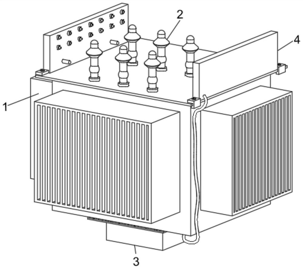
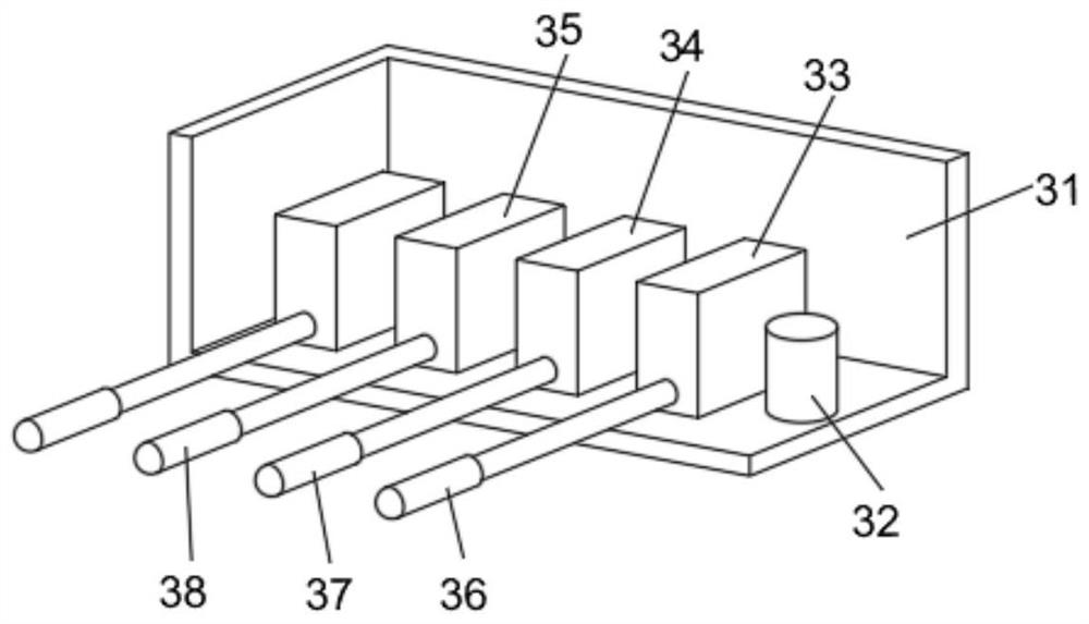
[0032] The present invention will be further described below with reference to the accompanying drawings and embodiments.

[0033] Please refer to Figure 1-Figure 8 ,in, figure 1 A schematic structural diagram of a preferred embodiment of the transformer operation monitoring device provided by the present invention; figure 2 is a schematic structural diagram of the monitoring assembly in the present invention; 3 is a structural schematic diagram of the interior of the installation box in the present invention; Figure 4 It is a schematic diagram of the explosion structure of the connector in the present invention; Figure 5 It is a structural schematic diagram of the fireproof assembly in the present invention; Image 6 It is a schematic structural diagram of the interior of the fireproof board in the present invention; Figure 7 It is a schematic structural diagram of the air pump in the present invention; Figure 8 It is a schematic diagram of the structure of the mou...


PUM


Abstract

The invention provides a transformer operation monitoring device. The transformer operation monitoring device comprises a transformer, and the upper end of the transformer is provided with a connector. The monitoring assembly used for monitoring operation of the transformer in real time is installed at the bottom of the transformer; the fireproof assembly used for extinguishing fire when the monitoring assembly detects that the transformer has a fire disaster is mounted at the upper end of the transformer, the fireproof assembly comprises a fireproof plate, a fire extinguishing cavity and an electric control spray head, the fireproof plate is fixedly mounted at the upper end of the transformer through a mounting piece, and the fire extinguishing cavity for storing a fire extinguishing material is formed in the fireproof plate; the electric control nozzle is installed on the fireproof plate and communicates with the interior of the fire extinguishing cavity. According to the transformer, the monitoring assembly and the fire extinguishing assembly are installed on the transformer, the running state of the transformer is monitored in real time, meanwhile, a fire source can be extinguished in time, potential safety hazards caused by fire diffusion are prevented, large losses are avoided, and the use safety of the transformer is improved.

Description

technical field [0001] The invention relates to the field of transformers, in particular to a transformer operation monitoring device. Background technique [0002] A transformer refers to a device that uses the principle of electromagnetic induction to change the AC voltage. Its main components are the primary coil, the secondary coil and the iron core (magnetic core). The main functions of transformers are: voltage transformation, current transformation, impedance transformation, isolation, voltage regulation (magnetic saturation transformer), etc., and can be divided into: power transformers and special transformers according to their uses. [0003] In electrical equipment and wireless circuits, transformers are often used for voltage reduction, impedance matching, and safety isolation. In the generator, whether the coil moves through the magnetic field or the magnetic field moves through the fixed coil, an electric potential can be induced in the coil. In both cases, th...

Claims


Application Information

Patent Timeline
IPC IPC(8): A62C3/16G01D21/02
Inventor 唐成自
Owner 江苏天瑞变压器有限公司
Why Eureka
Try Eureka