Solution dehumidification unit based on return air cooling capacity recovery

A solution dehumidification and unit technology, applied in energy recovery systems for ventilation and heating, ventilation systems, mechanical equipment, etc., can solve the problems of single operation mode, large energy consumption, high operation and maintenance costs, and achieve energy cost reduction and efficient utilization , Improve the effect of the production environment

Pending Publication Date: 2022-04-01
臣功(北京)科技有限公司
View PDF0 Cites 2 Cited by
  • Summary
  • Abstract
  • Description
  • Claims
  • Application Information

AI Technical Summary

Problems solved by technology

When using solution dehumidification in these occasions, because of the heat released during the solution dehumidification process, it is often necessary to be equipped with cooling and solution regeneration facilities. The operation mode is single, the energy consumption is huge, and the operation and maintenance costs are high.

Method used


Image

  • Solution dehumidification unit based on return air cooling capacity recovery

Examples


Embodiment Construction

[0019] In order to make the technical problems, technical solutions and beneficial effects to be solved by the present invention clearer, the present invention will be further described in detail in combination with the embodiments and accompanying drawings. It should be understood that the specific embodiments described here are only used to explain the present invention, not to limit the present invention. The technical solutions of the present invention will be described in detail below in conjunction with the embodiments and accompanying drawings, but the scope of protection is not limited thereto.

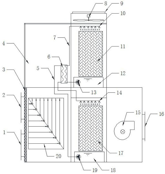
[0020] Such as figure 1 As shown, the present invention provides a solution dehumidification unit based on return air cooling capacity recovery, including a unit casing 4, and the unit casing 4 is respectively provided with a return air inlet 2, a return air outlet 9, a fresh air inlet 1, a fresh air The air outlet 16, the fresh air inlet 1 and the return air inlet 2 are arra...


PUM


Abstract

The invention relates to a solution dehumidification unit based on return air cooling capacity recovery, and belongs to the technical field of solution dehumidification. Comprising a unit shell, a fresh air inlet and a return air inlet are formed in one side of the shell, a fresh air outlet is formed in the other side of the shell, a return air outlet is formed in the upper side of the shell, and a filter, a fresh air and return air heat exchanger, a direct evaporation section and an axial flow fan are sequentially arranged in the shell in the flow direction of return air. A filter, a fresh air and return air heat exchanger, a solution dehumidification section and an air feeder are sequentially arranged in the shell in the flowing direction of fresh air. Compared with an existing solution dehumidification unit, a return air cooling capacity recycling method is directly utilized, heat released by solution heat absorption is reduced, fresh air solution dehumidification is achieved on the premise that return air cooling capacity is recycled, compared with a traditional solution dehumidification unit needing a matched refrigerating unit, the operation energy consumption of dehumidification is greatly reduced, energy is saved, environment is protected, and the energy-saving and environment-friendly effects are achieved. And the practicability is very high.

Description

technical field [0001] The invention belongs to the technical field of solution dehumidification, and in particular relates to a solution dehumidification unit based on recovery of return air cooling capacity. Background technique [0002] With the development of economic construction, especially in various precision processing industries, data centers, power distribution rooms and other places, it is necessary to dehumidify the factory buildings or machine rooms. When solution dehumidification is used in these occasions, because of the heat released during the solution dehumidification process, it is often necessary to be equipped with cooling and solution regeneration facilities. The operation mode is single, the energy consumption is huge, and the operation and maintenance costs are high. [0003] Under the background of the country’s proposal of carbon peaking and carbon neutralization, it may be necessary to fully recover the indoor cooling capacity, do a good job in th...

Claims


Application Information

Patent Timeline
Patent Type & Authority Applications(China)
IPC IPC(8): F24F3/14F24F5/00F24F7/003F24F8/108F24F12/00F24F13/28F24F13/30
Inventor 孙俊彪孙宁志黄德祥
Owner 臣功(北京)科技有限公司
Why Eureka
Try Eureka